

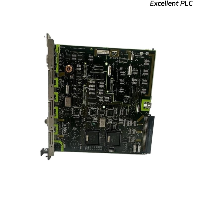
The Yokogawa AIP125 PLC Module Board is an industrial interface module equipped with connectors, plugs, and terminal blocks that provide electrical connections between controllers, I/O modules, communication networks, power supplies, and field devices. Because the module serves as a critical signal distribution component within Yokogawa Distributed Control Systems (DCS) and PLC-based automation systems, installation errors, loose wiring, damaged connectors, or environmental conditions can directly affect system communication and process reliability. A systematic troubleshooting procedure helps maintenance engineers quickly identify faults, restore normal operation, and reduce production downtime.
Contents
- 1. Understanding Module Fault Conditions
- 2. Common Failure Symptoms
- 3. Typical Causes of Faults
- 4. Initial Hardware Inspection
- 5. Power and Wiring Diagnostics
- 6. Communication Diagnostics
- 7. Connector and Terminal Inspection
- 8. Diagnostic Analysis
- 9. Recommended Troubleshooting Workflow
- 10. Corrective Actions
- 11. Functional Recovery Verification
- 12. Preventive Maintenance
- 13. Real Industrial Maintenance Case
- 14. Frequently Asked Questions
Understanding Module Fault Conditions
The AIP125 module distributes power and process signals through industrial connectors and terminal interfaces. Any interruption in these electrical paths may result in communication failures, unstable field signals, controller alarms, or complete loss of I/O communication.
Typical faults include loose terminals, damaged connectors, wiring errors, communication interruptions, poor grounding, corrosion, excessive vibration, and mechanical damage.
Common Failure Symptoms
- Loss of communication with connected modules.
- Intermittent field signal fluctuations.
- I/O channel failures.
- Unexpected controller alarms.
- Power distribution abnormalities.
- Connector overheating.
- Terminal block faults.
- Communication timeout errors.
Typical Causes of Faults
- Loose terminal screws.
- Damaged connector pins.
- Incorrect field wiring.
- Broken communication cables.
- Corroded electrical contacts.
- Poor cabinet grounding.
- Mechanical vibration.
- Contamination from dust or moisture.
Initial Hardware Inspection
- Inspect the module housing.
- Verify connector engagement.
- Check terminal blocks for damage.
- Inspect wiring labels.
- Verify cabinet ventilation.
Power and Wiring Diagnostics
- Measure supply voltage.
- Verify wiring continuity.
- Inspect fuse protection.
- Check polarity.
- Inspect cable insulation.
Communication Diagnostics
- Inspect communication connectors.
- Verify cable integrity.
- Check network configuration.
- Review controller communication status.
- Verify signal continuity.
Connector and Terminal Inspection
- Retighten terminal screws to the specified torque.
- Inspect connector pins for bending.
- Clean oxidized contacts.
- Replace damaged plugs.
- Verify correct cable routing.
Diagnostic Analysis
| Observed Condition | Possible Diagnosis |
|---|---|
| No communication | Loose connector or damaged communication cable |
| Unstable field signals | Loose terminal or poor electrical contact |
| Controller communication alarm | Incorrect wiring or connector fault |
| Voltage drop | High-resistance terminal connection |
| Connector overheating | Loose connection or excessive current |
Always inspect mechanical connections before replacing the module, as most field faults originate from wiring or connector issues rather than PCB failures.
Recommended Troubleshooting Workflow
VERIFY POWER SUPPLY
CHECK MODULE INSTALLATION
INSPECT CONNECTORS
VERIFY TERMINAL WIRING
CHECK COMMUNICATION
REVIEW DIAGNOSTIC ALARMS
IDENTIFY ROOT CAUSE
IMPLEMENT CORRECTIVE ACTION
VERIFY SYSTEM OPERATION
MONITOR PERFORMANCE
A structured troubleshooting process minimizes maintenance time and avoids unnecessary replacement of functional hardware.
Corrective Actions
- Retighten all terminal screws.
- Replace damaged connectors or plugs.
- Repair or replace communication cables.
- Correct wiring errors.
- Clean contaminated electrical contacts.
- Improve cabinet grounding.
- Replace damaged terminal blocks.
- Replace the module only after eliminating all external causes.
Functional Recovery Verification
- Verify stable module operation.
- Confirm normal communication.
- Validate field signal integrity.
- Review controller diagnostic information.
- Monitor system performance during production.
Preventive Maintenance
- Inspect terminal tightness during scheduled maintenance.
- Clean connectors regularly.
- Inspect wiring insulation.
- Review communication diagnostics.
- Maintain accurate wiring documentation.
Real Industrial Maintenance Case
During annual maintenance at a wastewater treatment facility, operators reported intermittent analog input fluctuations affecting several process measurements.
Inspection of the AIP125 module revealed oxidation on multiple terminal contacts caused by long-term exposure to humidity inside the control cabinet.
After cleaning the contacts, replacing one damaged connector, and retightening all terminals:
- Signal fluctuations disappeared.
- Communication stabilized.
- No additional controller alarms occurred.
- The automation system resumed reliable operation.
Frequently Asked Questions
Why do field signals become unstable?
The most common causes are loose terminal screws, oxidized contacts, damaged connectors, poor grounding, or improperly routed cables.
Can connector damage cause communication failures?
Yes. Bent pins, worn plugs, loose connectors, or damaged communication cables frequently interrupt signal transmission between controllers and field devices.
When should the AIP125 module be replaced?
The module should only be replaced after verifying that wiring, connectors, terminal blocks, grounding, power supplies, and communication cables are functioning correctly and diagnostic evidence confirms an internal hardware failure.
Summary
Effective troubleshooting of the Yokogawa AIP125 PLC Module Board requires systematic inspection of connectors, plugs, terminal blocks, wiring integrity, communication paths, grounding, and electrical continuity. Following a structured maintenance methodology improves system reliability, reduces downtime, and prevents unnecessary replacement of industrial automation hardware.