

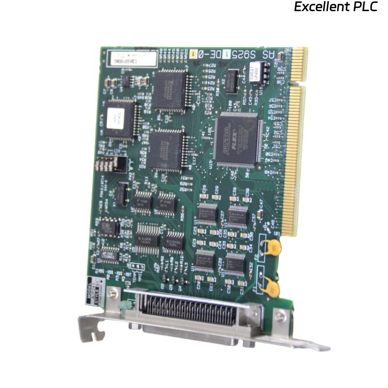
The Yokogawa AIP261 Interface Expansion Card is a backplane-integrated expansion module used in Yokogawa Distributed Control Systems (DCS) to increase system interface capacity and support scalable control architectures. It connects directly to the system backplane and relies on stable slot seating, power distribution, and internal bus communication for proper operation. Failures such as module non-detection, slot configuration errors, backplane communication faults, or intermittent expansion loss can disrupt system scalability and data exchange. A structured troubleshooting approach is essential to quickly identify faults and restore system integrity.
Contents
- 1. Understanding Expansion Card Faults
- 2. Common Failure Symptoms
- 3. Typical Causes of Faults
- 4. Initial Hardware Inspection
- 5. Power and Backplane Diagnostics
- 6. Slot Detection Diagnostics
- 7. Backplane Communication Checks
- 8. Configuration Verification
- 9. Diagnostic Log Analysis
- 10. Recommended Troubleshooting Workflow
- 11. Corrective Actions
- 12. Functional Recovery Verification
- 13. Preventive Maintenance
- 14. Real Industrial Maintenance Case
- 15. Frequently Asked Questions
Understanding Expansion Card Faults
The AIP261 depends on proper physical seating in the rack slot and stable backplane communication to integrate into the control system. Any disruption in mechanical alignment, power distribution, or configuration mapping can prevent the system from recognizing the card or cause intermittent communication loss.
Common Failure Symptoms
- Module not detected by engineering station.
- Slot shows empty or invalid status.
- Intermittent expansion interface availability.
- Backplane communication alarm.
- Configuration download failure.
- System mismatch or address conflict errors.
- Unexpected module reset.
- Loss of expanded I/O or communication channels.
Typical Causes of Faults
- Improper card insertion into slot.
- Backplane connector contamination or damage.
- Slot address configuration mismatch.
- Insufficient rack power supply.
- Firmware or system version incompatibility.
- Physical vibration causing partial disconnection.
- Faulty backplane bus communication.
- Internal expansion card hardware failure.
Initial Hardware Inspection
- Verify module is fully seated in slot.
- Inspect backplane connector pins.
- Check rack alignment and locking mechanism.
- Inspect for dust or oxidation.
- Verify rack power indicators.
Power and Backplane Diagnostics
- Verify rack power supply voltage.
- Check load distribution across modules.
- Inspect backplane power rails.
- Verify redundant power operation if available.
- Check for power-related alarms.
Slot Detection Diagnostics
- Verify correct slot number assignment.
- Confirm physical vs logical mapping.
- Check engineering station configuration.
- Verify no duplicate addressing.
- Reload configuration if needed.
Backplane Communication Checks
- Verify bus communication status.
- Check internal rack communication indicators.
- Monitor system error counters.
- Test communication with other modules.
- Verify synchronization signals.
Configuration Verification
- Confirm AIP261 is included in system database.
- Verify firmware compatibility.
- Check system version alignment.
- Reload configuration from engineering station.
- Ensure no parameter mismatch exists.
Diagnostic Log Analysis
| Observed Condition | Possible Diagnosis |
|---|---|
| Module not detected | Improper seating or backplane contact failure |
| Slot error | Configuration mismatch or address conflict |
| Intermittent detection | Vibration or loose backplane connection |
| Communication failure | Backplane bus fault or power instability |
| System reset | Power fluctuation or hardware instability |
Most AIP261 faults originate from mechanical or configuration issues rather than internal electronic failure.
Recommended Troubleshooting Workflow
VERIFY PHYSICAL SEATING
CHECK SLOT CONFIGURATION
VERIFY BACKPLANE POWER
INSPECT CONNECTORS
CHECK SYSTEM DETECTION
REVIEW CONFIGURATION DATABASE
IDENTIFY ROOT CAUSE
IMPLEMENT CORRECTIVE ACTION
VERIFY MODULE RECOGNITION
MONITOR SYSTEM STABILITY
A structured workflow significantly reduces downtime and prevents unnecessary hardware replacement.
Corrective Actions
- Reseat expansion card firmly in slot.
- Clean backplane connector contacts.
- Correct slot configuration mapping.
- Replace damaged rack connectors if needed.
- Stabilize rack power supply.
- Update system firmware if incompatible.
- Replace module only after confirming internal failure.
Functional Recovery Verification
- Verify module detection in engineering system.
- Confirm correct slot identification.
- Validate expanded interface availability.
- Review diagnostic logs.
- Monitor stable operation under load.
Preventive Maintenance
- Inspect rack connectors periodically.
- Ensure proper module seating during maintenance.
- Clean backplane contacts during shutdowns.
- Monitor rack vibration levels.
- Maintain updated configuration backups.
Real Industrial Maintenance Case
During a system upgrade in a refinery control room, the AIP261 expansion card was not recognized after installation.
Inspection revealed that slight misalignment prevented full engagement with the backplane connector due to uneven rack guide rails.
After realigning and reseating the card:
- The system detected the module immediately.
- Slot mapping corrected automatically.
- Expansion interfaces became active.
- The control system returned to stable operation.
Frequently Asked Questions
Why is the AIP261 not detected?
Most commonly due to improper seating, slot configuration mismatch, or backplane connector contact issues.
Can vibration cause faults?
Yes. Long-term vibration can loosen card seating or degrade backplane contact integrity, leading to intermittent detection.
When should the module be replaced?
Only after confirming correct slot installation, power stability, configuration accuracy, and backplane integrity, and ruling out all external causes.
Summary
Effective troubleshooting of the Yokogawa AIP261 Interface Expansion Card requires systematic verification of physical seating, slot configuration, backplane power integrity, communication bus health, and system configuration. Following a structured diagnostic process ensures reliable system expansion, minimizes downtime, and prevents unnecessary replacement of hardware components.