 Excellent PLC


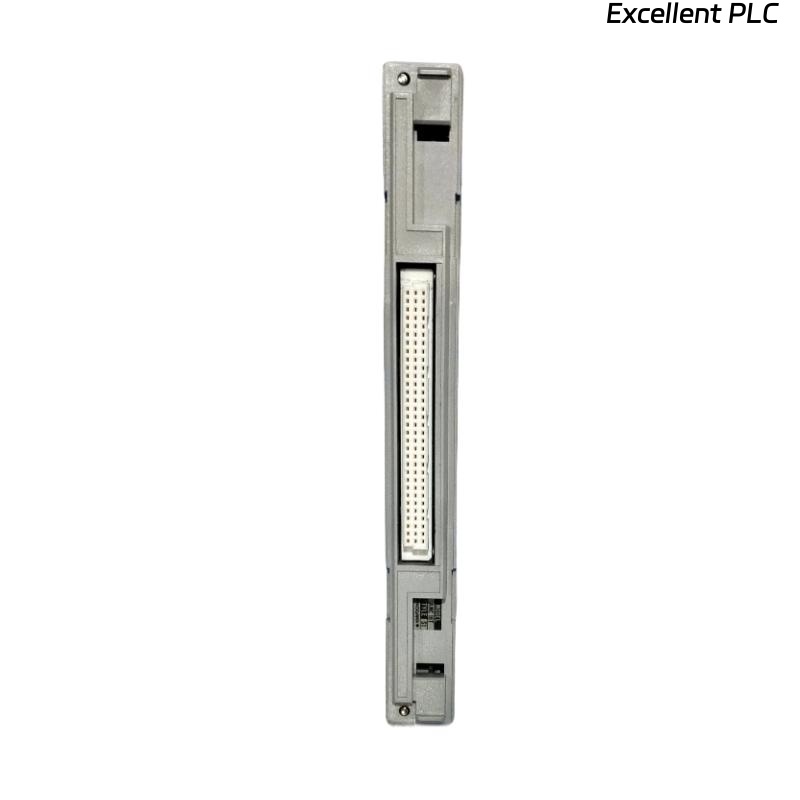
The Yokogawa AMM25C mV Input Multiplexer Module with Thermocouple Interface is a high-precision analog input module used in Yokogawa CENTUM CS and CENTUM VP Distributed Control Systems (DCS). The module acquires multiple low-level millivolt (mV) signals and thermocouple inputs through multiplexing technology while utilizing an integrated Reference Junction Compensation (RJC) circuit to improve temperature measurement accuracy. It is widely used in furnaces, boilers, reactors, kilns, heat exchangers, process analyzers, and other industrial temperature monitoring applications. Stable operation depends on proper thermocouple wiring, correct RJC operation, accurate channel configuration, effective shielding, and healthy module electronics. This guide provides a systematic troubleshooting procedure for diagnosing AMM25C faults and restoring reliable temperature measurement.
Contents
- 1. Understanding Module Faults
- 2. Common Failure Symptoms
- 3. Typical Causes
- 4. Initial Hardware Inspection
- 5. Thermocouple and mV Signal Verification
- 6. Diagnostic Analysis
- 7. Recommended Troubleshooting Workflow
- 8. Corrective Actions
- 9. Functional Recovery Verification
- 10. Preventive Maintenance
- 11. Industrial Maintenance Case
- 12. Frequently Asked Questions
Understanding Module Faults
The AMM25C scans multiple millivolt and thermocouple input channels sequentially and converts the measured values into digital process data. Accurate operation requires correct thermocouple type configuration, proper sensor polarity, functional reference junction compensation (RJC), compatible extension cables, secure wiring, and stable electrical conditions. Measurement errors commonly result from incorrect thermocouple configuration, damaged extension cables, RJC failures, grounding problems, electromagnetic interference, or internal module faults.
Common Failure Symptoms
- No temperature measurement.
- Incorrect temperature indication.
- Large temperature offset.
- Open thermocouple alarm.
- Unstable temperature readings.
- Multiple channel measurement errors.
- Reference Junction Compensation fault.
- Module diagnostic alarms.
Typical Causes
- Open thermocouple circuit.
- Incorrect thermocouple polarity.
- Wrong thermocouple type selected.
- Faulty or disconnected RJC sensor.
- Incorrect thermocouple extension cable.
- Poor shielding or grounding.
- Electrical interference.
- Internal AMM25C hardware failure.
Initial Hardware Inspection
- Verify the AMM25C is fully installed in the I/O base.
- Inspect connector locking mechanisms.
- Check thermocouple wiring.
- Inspect the RJC connection.
- Verify controller power supply.
- Inspect module diagnostic indicators.
Thermocouple and mV Signal Verification
- Verify thermocouple polarity.
- Confirm the configured thermocouple type matches the installed sensor.
- Measure thermocouple continuity.
- Inspect thermocouple extension cables.
- Verify RJC operation.
- Check shielding and grounding.
- Verify sensor installation.
Diagnostic Analysis
| Observed Condition | Possible Diagnosis |
|---|---|
| No temperature value | Open sensor circuit or module fault |
| Incorrect temperature | Wrong thermocouple type or RJC malfunction |
| Large measurement offset | Reference Junction Compensation failure |
| Temperature fluctuations | Electrical interference or loose wiring |
| Multiple channel failures | Power supply issue or internal module hardware failure |
Recommended Troubleshooting Workflow
CHECK MODULE STATUS
VERIFY POWER SUPPLY
INSPECT THERMOCOUPLE WIRING
VERIFY SENSOR POLARITY
CHECK RJC CONNECTION
VERIFY THERMOCOUPLE TYPE
CHECK DIAGNOSTICS
CONFIRM NORMAL OPERATION
Corrective Actions
- Reconnect loose wiring.
- Replace damaged thermocouples.
- Correct polarity errors.
- Select the correct thermocouple type.
- Repair or replace the RJC connection if faulty.
- Replace incorrect extension cable with matching thermocouple cable.
- Improve cable shielding and grounding.
- Replace the AMM25C module if internal hardware failure is confirmed.
Functional Recovery Verification
- Verify all configured channels operate correctly.
- Compare measured temperatures with calibrated reference equipment.
- Confirm proper RJC operation.
- Verify alarm functionality.
- Monitor long-term measurement stability.
Preventive Maintenance
- Inspect thermocouple wiring regularly.
- Verify connector security.
- Inspect RJC wiring during scheduled maintenance.
- Review module diagnostic logs.
- Verify sensor calibration periodically.
- Maintain clean cabinet ventilation.
Industrial Maintenance Case
At a petrochemical processing plant, operators reported that all furnace temperature readings connected to an AMM25C module were approximately 12°C higher than expected following routine maintenance.
Inspection revealed that the Reference Junction Compensation (RJC) connector had not been fully seated after cabinet servicing. Once the RJC connection was properly restored and thermocouple configuration verified:
- Temperature readings immediately returned to normal.
- Measurements matched portable calibration equipment.
- All alarm functions operated correctly.
- No additional temperature deviations occurred during continuous plant operation.
Frequently Asked Questions
Why are all temperature readings offset by a similar value?
A common cause is a faulty or disconnected Reference Junction Compensation (RJC) circuit, incorrect thermocouple configuration, or the use of incompatible thermocouple extension cable.
Why does the module report an open thermocouple alarm?
This usually indicates a broken thermocouple, disconnected wiring, damaged extension cable, loose connector, or poor terminal contact.
What should be checked before replacing the AMM25C?
Verify thermocouple continuity, polarity, extension cable type, RJC operation, wiring integrity, software configuration, grounding, controller diagnostics, and sensor calibration before determining that the module itself has failed.
Summary
Effective troubleshooting of the Yokogawa AMM25C mV Input Multiplexer Module with Thermocouple Interface requires systematic verification of module installation, thermocouple wiring, reference junction compensation, sensor configuration, grounding, shielding, and controller diagnostics. Routine preventive maintenance, proper RJC operation, and periodic calibration verification ensure accurate multi-channel temperature measurement and reliable long-term operation in Yokogawa CENTUM Distributed Control Systems.