 Excellent PLC


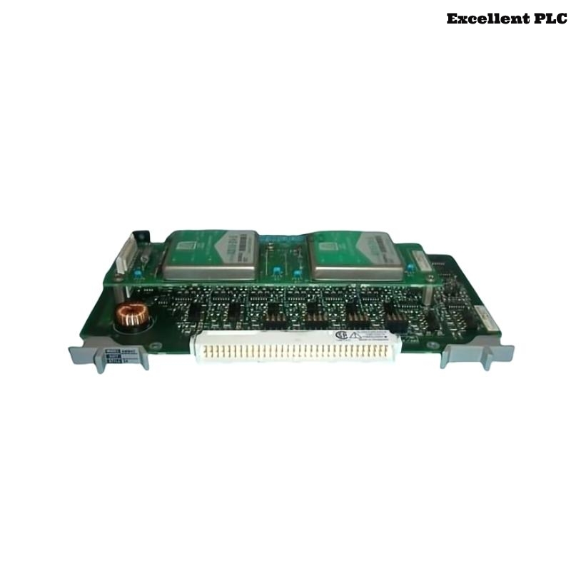
The Yokogawa AMM42-S3 Input Multiplexer Module is a multi-channel analog input multiplexer module used in Yokogawa CENTUM CS 3000 and CENTUM VP Distributed Control Systems (DCS). The module collects multiple field transmitter signals through multiplexing technology and transfers process measurements to the controller for monitoring and control. It is commonly used with two-wire transmitters such as pressure, flow, level, temperature, and analyzer instruments. Reliable operation depends on correct field wiring, stable transmitter power supply, proper channel configuration, secure connectors, and effective grounding. This guide provides a systematic troubleshooting procedure for diagnosing AMM42-S3 signal problems and restoring normal operation.
Contents
- 1. Understanding Module Faults
- 2. Common Failure Symptoms
- 3. Typical Causes
- 4. Initial Hardware Inspection
- 5. Field Signal Verification
- 6. Diagnostic Analysis
- 7. Recommended Troubleshooting Workflow
- 8. Corrective Actions
- 9. Functional Recovery Verification
- 10. Preventive Maintenance
- 11. Industrial Maintenance Case
- 12. Frequently Asked Questions
Understanding Module Faults
The AMM42-S3 scans multiple transmitter input channels and converts field signals into digital process values. Since industrial transmitter loops are sensitive to wiring quality, power stability, and electrical interference, abnormal measurements may result from open loops, incorrect polarity, transmitter failures, incorrect configuration, grounding problems, or module hardware faults.
Common Failure Symptoms
- No transmitter signal displayed.
- Input value remains fixed.
- Signal intermittently disappears.
- Incorrect process values.
- Multiple transmitter channels fail simultaneously.
- Communication or diagnostic alarms appear.
- Input values fluctuate abnormally.
Typical Causes
- Open field wiring circuit.
- Incorrect transmitter polarity.
- Loss of transmitter power supply.
- Loose connector or terminal connection.
- Incorrect DCS channel configuration.
- Faulty field transmitter.
- Electrical noise interference.
- Internal AMM42-S3 module failure.
Initial Hardware Inspection
- Verify the AMM42-S3 module is properly installed.
- Check module connector locking condition.
- Inspect field wiring terminals.
- Verify transmitter power supply voltage.
- Check module diagnostic status.
Field Signal Verification
- Measure transmitter loop current with a calibrated meter.
- Verify current loop polarity.
- Confirm transmitter supply voltage.
- Check cable continuity.
- Inspect cable shielding and grounding.
- Verify transmitter output independently.
Diagnostic Analysis
| Observed Condition | Possible Diagnosis |
|---|---|
| No signal from one channel | Transmitter fault, wiring problem, or channel fault |
| All channels lost | Power supply problem or module communication failure |
| Signal fluctuates | Electrical interference or poor grounding |
| Incorrect process value | Scaling/configuration error or transmitter calibration issue |
| Intermittent signal loss | Loose connector or unstable field wiring |
Recommended Troubleshooting Workflow
CHECK MODULE STATUS
VERIFY POWER SUPPLY
INSPECT CONNECTORS
CHECK FIELD TRANSMITTER
MEASURE LOOP SIGNAL
VERIFY CHANNEL CONFIGURATION
CHECK DIAGNOSTICS
CONFIRM NORMAL OPERATION
Corrective Actions
- Reconnect loose terminals and connectors.
- Repair damaged field cables.
- Restore transmitter power supply.
- Correct transmitter polarity.
- Correct DCS configuration parameters.
- Replace failed field transmitters.
- Improve shielding and grounding.
- Replace AMM42-S3 module if internal failure is confirmed.
Functional Recovery Verification
- Verify all input channels return to normal.
- Compare readings with calibrated field instruments.
- Confirm correct engineering unit scaling.
- Verify alarms and diagnostics are cleared.
- Monitor long-term signal stability.
Preventive Maintenance
- Inspect field wiring periodically.
- Check connector tightness.
- Verify transmitter power supplies.
- Review DCS diagnostic records.
- Perform regular loop calibration checks.
- Maintain proper cabinet environmental conditions.
Industrial Maintenance Case
At a chemical processing plant, several pressure transmitters connected through an AMM42-S3 module suddenly displayed invalid process values after an instrument cabinet inspection.
Maintenance investigation found that the multiplexer field connector had not been fully locked after inspection work, causing intermittent contact across several channels. After reseating the connector, checking loop currents, and verifying channel configuration:
- All transmitter signals recovered.
- Process values matched field indicators.
- Diagnostic alarms cleared.
- The DCS returned to stable operation.
Frequently Asked Questions
Why does only one transmitter channel fail?
A single failed channel is usually caused by a faulty transmitter, damaged field cable, incorrect wiring, or an individual channel problem.
Why do multiple channels fail at the same time?
Multiple failures usually indicate a common cause such as power supply loss, connector problems, grounding issues, communication faults, or module hardware failure.
What should be checked before replacing the AMM42-S3?
Verify transmitter operation, loop current, power supply, wiring integrity, connector condition, channel configuration, grounding, and diagnostic information before replacing the module.
Summary
Effective troubleshooting of the Yokogawa AMM42-S3 Input Multiplexer Module requires systematic verification of field wiring, transmitter power supply, connector integrity, channel configuration, grounding, shielding, and DCS diagnostics. Proper maintenance and timely correction of field signal problems ensure reliable multi-channel process measurement and long-term Yokogawa CENTUM system performance.