 Excellent PLC


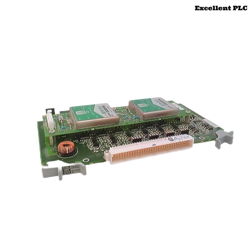
The Yokogawa AMM42-S4 Power Supply Module is a power supply unit used in Yokogawa Distributed Control Systems (DCS) and Remote I/O system configurations. The module provides stable power for associated I/O modules, communication modules, and control system components. Since power quality directly affects the operation of field signal acquisition and communication equipment, AMM42-S4 faults may result in multiple system alarms, I/O failures, communication interruptions, or controller abnormalities. This troubleshooting guide provides a systematic method for identifying power-related problems and restoring reliable operation.
Contents
- 1. Understanding Power Module Faults
- 2. Common Failure Symptoms
- 3. Typical Causes
- 4. Initial Hardware Inspection
- 5. Power Input and Output Verification
- 6. Diagnostic Analysis
- 7. Recommended Troubleshooting Workflow
- 8. Corrective Actions
- 9. Functional Recovery Verification
- 10. Preventive Maintenance
- 11. Industrial Maintenance Case
- 12. Frequently Asked Questions
Understanding Power Module Faults
The AMM42-S4 supplies operating power to Yokogawa control system components. Any abnormality in input power, output voltage, wiring connection, grounding, thermal conditions, or internal power conversion circuits can affect downstream modules. Troubleshooting should begin with external power conditions before replacing the module.
Common Failure Symptoms
- Remote I/O modules lose power.
- Multiple I/O channels become unavailable.
- DCS reports communication failure.
- Power alarms appear.
- Module status indicators show abnormal conditions.
- System restarts unexpectedly.
- Output voltage fluctuates.
- Connected modules operate intermittently.
Typical Causes
- Loss of incoming AC power.
- Incorrect input voltage.
- Loose power terminals.
- Damaged power cables.
- Overloaded output circuit.
- Poor grounding.
- Insufficient cabinet cooling.
- Internal power supply component failure.
Initial Hardware Inspection
- Check AMM42-S4 installation position.
- Inspect module fixing condition.
- Verify power cable connections.
- Check terminal tightness.
- Inspect module status indicators.
- Check cabinet temperature and ventilation.
Power Input and Output Verification
- Measure incoming power voltage.
- Verify voltage is within system requirements.
- Measure AMM42-S4 output voltage.
- Check output stability under normal load.
- Inspect grounding connection.
- Verify downstream module power consumption.
Diagnostic Analysis
| Observed Condition | Possible Diagnosis |
|---|---|
| No output voltage | Input power failure or internal module fault |
| Low output voltage | Overload, wiring loss, or power conversion problem |
| Output fluctuation | Loose connection, unstable input, or aging components |
| Multiple I/O failures | Power distribution problem |
| Intermittent restart | Thermal issue or unstable power supply |
Recommended Troubleshooting Workflow
CHECK SYSTEM ALARMS
VERIFY INPUT POWER
CHECK POWER WIRING
MEASURE OUTPUT VOLTAGE
CHECK LOAD CONDITION
VERIFY GROUNDING
CHECK MODULE STATUS
CONFIRM NORMAL OPERATION
Corrective Actions
- Restore incoming power supply.
- Tighten loose terminals.
- Repair damaged power cables.
- Correct wiring polarity.
- Reduce excessive load.
- Improve cabinet ventilation.
- Repair grounding problems.
- Replace AMM42-S4 if internal power circuit failure is confirmed.
Functional Recovery Verification
- Confirm stable output voltage.
- Verify all connected I/O modules restart normally.
- Check DCS communication status.
- Confirm alarms are cleared.
- Monitor system operation under normal load.
Preventive Maintenance
- Inspect power terminals periodically.
- Check for signs of overheating.
- Verify cabinet ventilation.
- Review DCS power alarms.
- Inspect grounding connections.
- Monitor output voltage trends.
Industrial Maintenance Case
At a chemical production facility, several remote I/O stations intermittently disconnected from the control system during peak operating periods.
Maintenance personnel measured the AMM42-S4 output voltage and found periodic voltage drops. Further inspection identified excessive cabinet temperature caused by blocked ventilation filters, resulting in unstable power module operation. After cleaning the ventilation system and confirming stable power output:
- Remote I/O communication recovered.
- All connected modules operated normally.
- System alarms disappeared.
- No further power-related interruptions occurred.
Frequently Asked Questions
Why can one power module failure affect many system modules?
The AMM42-S4 supplies power to multiple downstream components. Any power interruption or instability can cause simultaneous failures across connected I/O and communication modules.
Why should voltage be measured before replacing the module?
Many apparent power module failures are actually caused by external issues such as wiring problems, unstable input power, excessive load, or poor cooling conditions.
What checks should be completed before replacement?
Verify input voltage, output voltage, wiring integrity, grounding, load conditions, cabinet temperature, and diagnostic information before replacing the AMM42-S4.
Summary
Effective troubleshooting of the Yokogawa AMM42-S4 Power Supply Module requires systematic verification of input power, wiring connections, output voltage, grounding, load conditions, environmental factors, and system diagnostics. Proper preventive maintenance and timely correction of power issues ensure stable operation of Yokogawa Distributed Control Systems and minimize unexpected process interruptions.