

Table of Contents
- Bently Nevada 177230-01-02-05 Troubleshooting Entry
- Signal Behavior in High-Range Seismic Sensors
- Diagnostic Flow for Fault Isolation
- Root Mechanisms Behind Measurement Errors
- Real Case: Signal Saturation Misinterpretation
- Recovery and Optimization Strategy
- FAQ
- Technical Summary
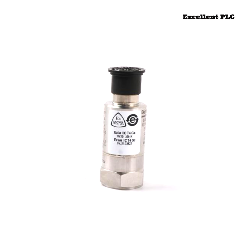
Bently Nevada 177230-01-02-05 Troubleshooting Entry
Bently Nevada 177230-01-02-05 seismic sensor troubleshooting reveals that abnormal signal behavior—such as early saturation, compressed output range, or unstable readings—is typically caused by configuration mismatch or installation issues rather than hardware failure.
This guide focuses on interpreting high-range signal behavior for accurate fault diagnosis.
Signal Behavior in High-Range Seismic Sensors
- Signal saturates before expected vibration level
- Output range compressed (e.g., 4–12 mA only)
- Signal fluctuates at high vibration levels
- Sudden clipping at high load
These patterns indicate configuration or installation problems.
Diagnostic Flow for Fault Isolation
IF signal saturates early:
    check PLC scaling
    verify sensor range

IF signal compressed:
    check installation location
    verify vibration transmission

IF signal fluctuates:
    inspect grounding and EMI

IF signal clipped:
    check mechanical overload or mounting
This diagnostic approach aligns with real field troubleshooting logic.
Root Mechanisms Behind Measurement Errors
- Mismatch between sensor range and PLC scaling
- Poor mechanical coupling reducing signal amplitude
- Electrical noise affecting high-range signals
- Incorrect installation location
Real Case: Signal Saturation Misinterpretation
In a turbine system, vibration readings quickly reached 20 mA during startup.
Observed Data:
- Signal saturated at low load (~30% speed)
- No abnormal mechanical vibration detected
Analysis: Measurement configuration suspected.
Root Cause: PLC configured for low-range sensor (0–12.7 mm/s).
Solution:
- Updated scaling to match high-range sensor
Result: Signal normalized across full operating range (5–17 mA).
Recovery and Optimization Strategy
- Align sensor range with system configuration
- Ensure rigid mounting for high vibration transfer
- Maintain proper grounding and shielding
- Perform periodic calibration verification
Correct configuration is critical for high-range monitoring systems.
FAQ
Why does the signal saturate too early?
This is usually caused by incorrect PLC scaling or configuration mismatch.
How to confirm installation issues?
Check mounting location and compare with vibration analyzer readings.
Is the sensor damaged if signal clips?
No, clipping is usually caused by configuration or installation issues.
Technical Summary
This Troubleshooting Guide shows that Bently Nevada 177230-01-02-05 faults are mainly caused by scaling mismatch, installation issues, and signal integrity problems. A structured diagnostic approach ensures accurate high-range vibration monitoring.