

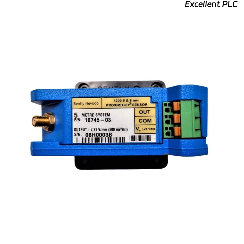
Bently Nevada 18745-03 Proximitor Sensor Installation Guide Focused on Signal Stability in 7200 Systems
Table of Contents
- Why Correct Installation of 18745-03 Is Often Missed
- What We Saw After a “Normal” Installation
- What Actually Determines Signal Quality
- How We Rebuilt the Installation Approach
- How We Verified the Installation Was Finally Correct
- 18745-03 Installation Best Practices from Field
- FAQ
- Technical Summary
Why Correct Installation of 18745-03 Is Often Missed
Bently Nevada 18745-03 proximitor sensor installation problems rarely come from wiring mistakes alone. In most real cases, the system is wired correctly — but the signal is still unusable.
The reason is simple:
installation is judged by connection, but performance depends on alignment.
What We Saw After a “Normal” Installation
In a steam turbine startup, the 7200 series system using 18745-03 showed:
- Stable wiring, no alarms
- But vibration trend drifting slowly upward
- Baseline voltage sitting at -5V instead of expected range
At that point, nothing looked “wrong” from installation checklist perspective.
What Actually Determines Signal Quality
After reviewing the system, we focused on three factors that are often underestimated:
- Probe gap relative to linear range
- Total system length matching (probe + cable + proximitor)
- Cable routing under electromagnetic interference
These are not just installation steps — they directly define whether the signal is usable.
IF gap_voltage > -6V:
    probe_too_far = TRUE
IF gap_voltage < -12V:
    probe_too_close = TRUE

IF system_length_mismatch:
    signal = distorted
How We Rebuilt the Installation Approach
Instead of reinstalling everything, we adjusted only what affects signal physics.
- Re-positioned probe to bring voltage into -8V to -10V range
- Verified total cable length matched 5 m system spec
- Separated sensor cable from motor power lines (minimum 30 cm)
One important detail:
we stopped treating installation as “mechanical mounting” and started treating it as signal calibration.
How We Verified the Installation Was Finally Correct
Instead of relying on system status, we validated using real data:
- Voltage stabilized at -9.1V
- Vibration trend became smooth (no spikes)
- Repeatability confirmed after multiple startups
This step is often skipped, but without it, installation cannot be considered complete.
18745-03 Installation Best Practices from Field
- Always use voltage as primary installation indicator, not just wiring check
- Do not assume correct gap without measurement
- Avoid tight cable bending near connectors
- Re-check system after thermal expansion (important for turbines)
FAQ
What is the correct voltage after installing 18745-03 proximitor sensor?
Typically between -8V and -10V, which represents the linear measurement range.
Why does vibration increase after installation even if wiring is correct?
This is usually caused by incorrect probe gap or system length mismatch affecting signal linearity.
Technical Summary
Bently Nevada 18745-03 proximitor sensor installation is not just about correct wiring but about achieving stable and linear signal output. Field experience shows that probe gap positioning, system length matching, and cable routing directly determine measurement reliability. Treating installation as a signal calibration process significantly improves system performance and reduces false vibration readings.