

Bently Nevada 1900/25-01-00 Vibration Monitor Installation Guide for System Configuration and Commissioning
Table of Contents
- Why 1900/25 Installation Impacts Measurement Accuracy
- How the 1900/25-01-00 Fits into the Vibration System
- Building the Complete Signal Chain
- Wiring and Power Configuration Strategy
- System Configuration and Parameter Setup
- Commissioning Based on Real Signal Behavior
- 1900/25 Installation Best Practices
- FAQ
- Technical Summary
Why 1900/25 Installation Impacts Measurement Accuracy
Bently Nevada 1900/25-01-00 vibration monitor installation errors typically do not cause immediate alarms, but they silently distort vibration data. In many field cases, systems appear operational while trending data becomes unreliable over time.
This happens because the monitor is not just a display unit — it interprets and scales analog signals from proximity sensors or velocity transducers. Any installation deviation propagates directly into measurement error.
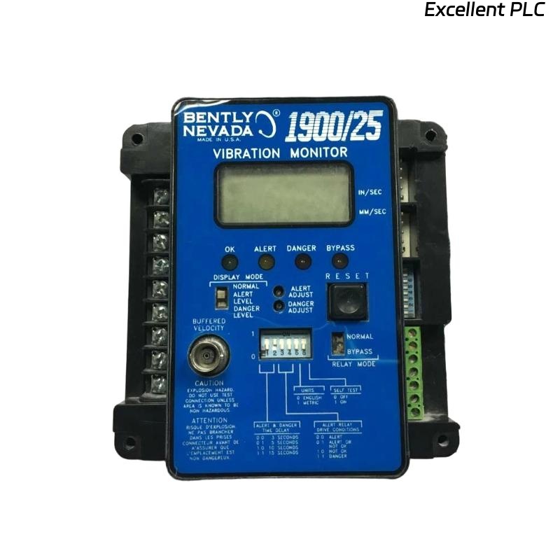
How the 1900/25-01-00 Fits into the Vibration System
The 1900/25 monitor acts as a compact vibration monitoring solution for small to medium rotating equipment. It typically interfaces with:
- Proximity probes (e.g., 7200 series)
- Velocity sensors (mV/mm/s output)
- 4–20 mA output loops for PLC or DCS
From a system configuration perspective, it sits between the sensor layer and control layer.
Building the Complete Signal Chain
A reliable installation starts with understanding the signal path:
- Sensor → Signal conditioning → 1900/25 input
- Internal scaling → alarm processing
- Output → relay / 4–20 mA / display
IF input_signal_range != configured_range:
    displayed_value = incorrect
    alarm_threshold = invalid
We observed a case where a velocity sensor (100 mV/mm/s) was connected but the monitor was configured for proximity input — resulting in a 3x error in displayed vibration.
Wiring and Power Configuration Strategy
The 1900/25-01-00 module requires stable DC power and clean signal wiring.
- Power input: typically 24 VDC (measured stable range: 23.5–24.5V)
- Separate signal and power grounding
- Use shielded cables for sensor input
In one installation, shared grounding caused noise injection, increasing baseline vibration by ~15%.
System Configuration and Parameter Setup
Configuration is where most hidden installation errors occur.
- Select correct sensor type (proximity / velocity)
- Set scaling factor (e.g., mV per unit)
- Define alarm thresholds based on machine standard
Example:
- Input signal: -10V to 0V (proximity)
- Configured range: 0–200 µm
If scaling is incorrect, alarm logic becomes meaningless even if wiring is correct.
Commissioning Based on Real Signal Behavior
Commissioning should not rely only on configuration confirmation — it must validate real signal behavior.
- Check steady-state vibration value
- Observe signal during startup and shutdown
- Compare with handheld vibration analyzer
Real case:
- Monitor reading: 60 µm
- Portable analyzer: 32 µm
- Root cause: scaling factor misconfigured
1900/25 Installation Best Practices
- Always verify sensor type before configuration
- Validate readings with independent measurement tool
- Avoid mixing signal types on same configuration logic
- Document configuration parameters for maintenance reference
FAQ
Why does the 1900/25 monitor show higher vibration than expected?
This is usually caused by incorrect scaling or wrong sensor type configuration.
Can the 1900/25 work with both proximity and velocity sensors?
Yes, but configuration must match the input signal characteristics exactly.
Technical Summary
Bently Nevada 1900/25-01-00 installation is fundamentally about correct signal interpretation rather than simple wiring. Field experience shows that most issues arise from configuration mismatch and signal scaling errors. A complete installation must include signal chain validation, parameter verification, and real-world commissioning to ensure reliable vibration monitoring performance.