

Bently Nevada 190501-00-00-00 Velomitor CT Speed Sensor Installation Guide for Accurate Measurement and Signal Integration
Table of Contents
- Why Accurate Installation of Velomitor CT Matters
- Common Installation Challenges
- Optimal Placement for Accurate Readings
- Wiring Best Practices
- Configuring the Sensor for Accuracy
- Commissioning the Velomitor CT Sensor
- Installation Best Practices
- FAQ
- Technical Summary
Why Accurate Installation of Velomitor CT Matters
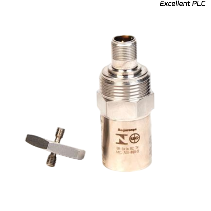
The Velomitor CT speed sensor provides high-precision speed measurements, essential for monitoring rotating equipment in high-speed applications. Proper installation ensures accurate data acquisition and reliable performance, especially in industrial settings where precision is key to machinery protection.
Common Installation Challenges
A typical challenge observed in the field:
- Misalignment between sensor and target
- Incorrect wiring configurations leading to inaccurate readings
- Environmental interference (e.g., EMI, vibration noise)
Optimal Placement for Accurate Readings
The sensor must be positioned such that the gap between the Velomitor CT and the rotating target (e.g., shaft) is consistently maintained within the manufacturer’s recommended range (usually 0.05 to 0.1 inches).
- Mount the sensor as close to the target as possible without causing physical contact.
- Avoid placing the sensor near sources of electromagnetic interference (EMI).
- Ensure that the mounting surface is rigid and free from vibration.
Wiring Best Practices
Proper wiring practices are essential to avoid signal degradation and electromagnetic interference:
- Use shielded cables to protect against external EMI.
- Ensure that the wiring does not run parallel to high-power lines.
- Keep the sensor wiring as short as possible to reduce signal loss.
- Ground the sensor to avoid floating signals.
Configuring the Sensor for Accuracy
- Set the correct signal range (0–5 VDC or 4–20 mA) based on your system’s requirements.
- Adjust the sensor’s gain to ensure it properly responds to the target speed range.
- Verify that the signal output is correctly mapped to the monitoring system or PLC.
Commissioning the Velomitor CT Sensor
After installation, commissioning should be performed to validate sensor functionality:
- Compare sensor output with manual speed measurements (e.g., using a handheld tachometer).
- Ensure that the sensor output is linear and proportional to speed.
- Verify that the sensor output does not drift over time.
Installation Best Practices
- Always verify alignment before securing the sensor in place.
- Ensure proper cable shielding to prevent signal interference.
- Use a torque wrench when mounting to avoid over-tightening and damaging the sensor.
- Perform a final calibration after all installation steps are completed.
FAQ
Why is proper alignment crucial for Velomitor CT sensor installation?
Proper alignment ensures that the sensor accurately detects the rotational movement of the target without any mechanical contact, which could result in false readings or damage to the sensor.
What should I do if the sensor output is erratic or unstable?
Check the wiring for any loose connections or signal interference. Ensure that the sensor is properly grounded, and verify that there is no physical contact with the target.
Technical Summary
Installing the Bently Nevada 190501-00-00-00 Velomitor CT speed sensor requires careful attention to sensor placement, wiring practices, and system configuration. Accurate installation is essential for ensuring reliable operation and precise speed measurement in rotating equipment applications.