

Table of Contents
- 200350-10-00-01 Accelerometer Installation Overview
- Role of 200350 Accelerometer in Monitoring Systems
- Mechanical Installation and Torque Control
- Signal Wiring and Power Requirements
- System Setup and Parameter Configuration
- Commissioning and Signal Verification
- Real Installation Case
- Installation FAQ
- Final Engineering Summary
200350-10-00-01 Accelerometer Installation Overview
Bently Nevada 200350-10-00-01 accelerometer installation errors typically lead to signal distortion rather than total signal loss. In most field cases, incorrect wiring or poor mounting introduces noise that is misinterpreted as mechanical vibration.
This Installation Guide focuses on ensuring proper mechanical coupling, stable signal transmission, and accurate system commissioning for industrial vibration monitoring.
Role of 200350 Accelerometer in Monitoring Systems
- Measures vibration acceleration up to ±50 g range
- Provides stable output with typical sensitivity of 100 mV/g
- Operates within 0.5–10,000 Hz frequency range
- Designed for harsh industrial environments with hermetic sealing :contentReference[oaicite:0]{index=0}
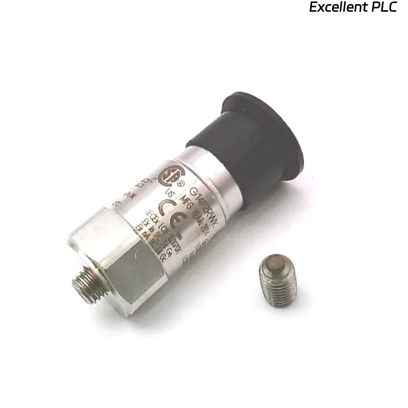
Mechanical Installation and Torque Control
- Use stud mounting (1/4-28 thread) for rigid coupling
- Mount directly on bearing housing, not covers
- Apply torque between 2.7–6.8 Nm
- Ensure clean metal surface (no paint or grease)
  // Mounting Validation Logic
  IF Surface_Not_Metal OR Loose_Mount THEN
      Reinstall_With_Stud();
  ELSE
      Proceed_To_Wiring();
  END_IF;
Signal Wiring and Power Requirements
- Supply constant current excitation (2–20 mA, 18–28 VDC typical)
- Output bias voltage should be 8–12 VDC
- Use shielded low-noise coaxial cable (max ~30 m recommended)
- Ground shield at control system side only
Incorrect wiring polarity or grounding can cause bias voltage drift and signal instability, even when the sensor itself is functioning normally.
System Setup and Parameter Configuration
- Set input type to IEPE / constant current accelerometer
- Configure sensitivity (100 mV/g)
- Convert to velocity (mm/s) if required by PLC Controller
- Set alarm thresholds based on baseline vibration data
Commissioning and Signal Verification
- Measure bias voltage (target: ~10 VDC)
- Run machine at idle (expected vibration: 1–4 mm/s typical)
- Check frequency spectrum (no abnormal peaks)
- Verify repeatability across multiple runs
Real Installation Case
In one compressor installation, abnormal vibration alarms appeared after startup:
- Measured: 9.2 mm/s (expected < 4 mm/s)
- Signal showed high-frequency noise
We observed that the sensor cable shield was grounded at both ends, creating a ground loop.
After correction:
- Shield grounded only at monitoring system side
- Improved cable routing away from motor power line
Result:
- Vibration reduced to 3.4 mm/s
- Signal stabilized with clean waveform
Installation FAQ
What is the correct power supply for 200350-10-00-01 accelerometer?
It requires constant current excitation (typically 2–20 mA) with supply voltage between 18–28 VDC.
Why is my signal unstable after installation?
Most likely due to grounding or shielding issues rather than sensor failure.
Can I extend the cable length beyond 30 meters?
It is possible but may introduce noise. Use low-capacitance cable and proper shielding.
Final Engineering Summary
The Bently Nevada 200350-10-00-01 Installation Guide emphasizes that reliable vibration data depends on correct wiring, grounding, and mechanical mounting. Proper commissioning ensures stable and accurate monitoring results.