 Excellent PLC


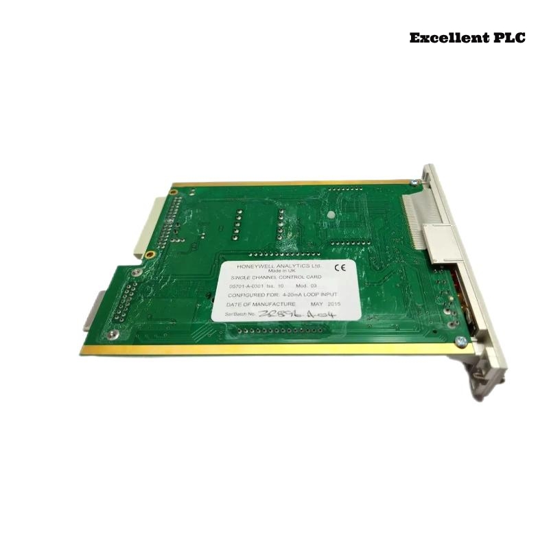
The Honeywell 05701-A-0301 Single Channel Control Card is a key component of the Honeywell System 57 Gas Detection Controller. It processes signals from compatible gas sensor interface modules, displays gas concentration values, manages alarm thresholds, and provides fault diagnostics for a single detection channel. During continuous industrial operation, problems such as incorrect gas readings, alarm failures, signal loss, communication faults, or card hardware errors may occur. A systematic troubleshooting process helps engineers identify the source of the problem and restore reliable gas monitoring performance.
Contents
- 1. Understanding Control Card Faults
- 2. Common Failure Symptoms
- 3. Typical Causes
- 4. Initial Hardware Inspection
- 5. Signal and Sensor Verification
- 6. Diagnostic Analysis
- 7. Recommended Troubleshooting Workflow
- 8. Corrective Actions
- 9. Functional Recovery Verification
- 10. Preventive Maintenance
- 11. Industrial Maintenance Case
- 12. Frequently Asked Questions
Understanding Control Card Faults
The Honeywell 05701-A-0301 controls one gas detection channel within the System 57 platform. It receives measurement signals from the sensor drive module, processes gas concentration data, activates alarms according to configured limits, and reports system faults. Abnormal operation may be caused by incorrect configuration, sensor problems, wiring faults, unstable power supply, contaminated connectors, calibration errors, or internal control card failure.
Common Failure Symptoms
- No gas concentration displayed.
- Incorrect gas concentration reading.
- Alarm output does not activate.
- False gas alarms occur.
- Fault indicator remains active.
- Sensor signal is unstable.
- Channel cannot complete calibration.
- Control card does not initialize correctly.
Typical Causes
- Incorrect sensor configuration.
- Failed or aging gas transmitter.
- Open circuit or short circuit in field wiring.
- Incorrect 4–20 mA signal scaling.
- Unstable controller power supply.
- Loose card connector.
- Corrupted configuration parameters.
- Sensor calibration drift.
- Internal electronic component failure.
Initial Hardware Inspection
- Check System 57 power supply status.
- Inspect 05701-A-0301 front indicators.
- Verify the card is fully inserted.
- Inspect rack connectors.
- Check associated sensor drive module.
- Review controller fault messages.
Signal and Sensor Verification
- Measure the 4–20 mA sensor loop current.
- Verify transmitter output.
- Check sensor wiring polarity.
- Inspect cable shielding.
- Verify sensor calibration status.
- Confirm correct gas detector type configuration.
Diagnostic Analysis
| Observed Condition | Possible Diagnosis |
|---|---|
| No gas display | Power failure, sensor signal loss, or card fault |
| Reading remains at zero | Sensor failure, incorrect scaling, or wiring issue |
| Reading remains at maximum value | Over-range signal or transmitter malfunction |
| Alarm does not activate | Incorrect alarm settings or relay/output fault |
| Frequent fault alarms | Sensor problem, wiring instability, or card malfunction |
Recommended Troubleshooting Workflow
CHECK SYSTEM FAULT INDICATIONS
VERIFY POWER SUPPLY
CHECK SENSOR DRIVE MODULE
VERIFY 4-20mA SIGNAL
INSPECT FIELD WIRING
CHECK CONFIGURATION SETTINGS
TEST ALARM FUNCTIONS
CONFIRM NORMAL OPERATION
Corrective Actions
- Restore stable controller power.
- Reseat the control card.
- Repair damaged field wiring.
- Correct sensor configuration parameters.
- Recalibrate the gas detector.
- Replace defective sensors.
- Clean or repair card connectors.
- Replace the control card after confirming internal failure.
Functional Recovery Verification
- Confirm correct gas concentration display.
- Verify sensor signal stability.
- Test alarm activation levels.
- Check fault monitoring functions.
- Verify relay outputs if installed.
- Monitor system operation after repair.
Preventive Maintenance
- Perform regular gas detector calibration.
- Inspect control card connectors.
- Review alarm history.
- Check sensor loop wiring.
- Maintain stable power supply conditions.
- Perform periodic functional gas testing.
Industrial Maintenance Case
A petrochemical plant reported that one System 57 gas detection channel displayed incorrect gas concentration values and generated repeated fault alarms. Engineers inspected the Honeywell 05701-A-0301 control card and found that the card was operating normally. Further testing identified a deteriorated sensor cable causing intermittent 4–20 mA signal fluctuations.
After replacing the damaged cable, recalibrating the gas transmitter, verifying alarm settings, and testing the channel response:
- The gas reading returned to normal.
- Fault alarms were cleared.
- Alarm outputs operated correctly.
- The detection channel resumed stable operation.
Frequently Asked Questions
Why does the 05701-A-0301 display incorrect gas readings?
Possible causes include sensor calibration errors, incorrect input configuration, unstable 4–20 mA signals, damaged wiring, or a faulty sensor transmitter.
Why does the alarm output not activate?
The cause may be incorrect alarm configuration, faulty relay connections, disabled alarm settings, or a problem with the control card output circuit.
When should the 05701-A-0301 be replaced?
The card should only be replaced after confirming that the sensor, wiring, power supply, configuration parameters, and associated sensor drive module are operating correctly while the control card continues to show internal faults.
Summary
Effective troubleshooting of the Honeywell 05701-A-0301 Single Channel Control Card requires checking power supply stability, sensor signals, 4–20 mA loop integrity, configuration parameters, alarm settings, and diagnostic information. Regular calibration and preventive maintenance help ensure reliable gas detection and long-term safety system performance.