 Excellent PLC


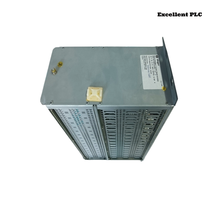
The Honeywell 05701-A-0511 is a 19-inch, 3U rear-access rack designed for the Honeywell System 57 Gas Detection Controller. It provides the mechanical structure, backplane, and power distribution required for the Engineering Card, DC Input Card, Single Channel Control Cards, and relay interface modules. Although the rack itself contains few active electronic components, problems involving the backplane, connectors, module seating, grounding, or field wiring can affect the operation of the entire gas detection system. A systematic troubleshooting procedure enables maintenance engineers to isolate rack-related faults efficiently and restore normal controller operation.
Contents
- 1. Understanding Rack Faults
- 2. Common Failure Symptoms
- 3. Typical Causes
- 4. Initial Hardware Inspection
- 5. Backplane and Connector Verification
- 6. Diagnostic Analysis
- 7. Recommended Troubleshooting Workflow
- 8. Corrective Actions
- 9. Functional Recovery Verification
- 10. Preventive Maintenance
- 11. Industrial Maintenance Case
- 12. Frequently Asked Questions
Understanding Rack Faults
The Honeywell 05701-A-0511 rack distributes power and communication signals through its integrated backplane. Faults associated with damaged connectors, poor module insertion, loose mounting hardware, contaminated backplane contacts, grounding problems, or damaged field wiring may prevent one or more modules from operating correctly. Since multiple controller cards depend on the rack infrastructure, a single mechanical fault can affect several gas detection channels simultaneously.
Common Failure Symptoms
- One or more control cards fail to power up.
- Engineering Card communication errors occur.
- Multiple gas detection channels become unavailable.
- Intermittent controller resets.
- Backplane communication failures.
- Modules are not recognized after installation.
- Random alarm or fault indications appear.
- Unstable system operation after vibration.
Typical Causes
- Loose module installation.
- Dirty or oxidized backplane connectors.
- Damaged rack backplane.
- Poor cabinet grounding.
- Loose rear field wiring.
- Mechanical damage during installation.
- Moisture or dust contamination.
- Improper rack mounting.
Initial Hardware Inspection
- Verify rack mounting security.
- Inspect the backplane connectors.
- Confirm all modules are fully inserted.
- Inspect rear wiring terminals.
- Verify cabinet grounding.
- Check for signs of moisture or contamination.
Backplane and Connector Verification
- Inspect connector pins for damage.
- Clean oxidized contacts using approved cleaning materials.
- Verify power distribution across the backplane.
- Check communication continuity between slots.
- Inspect connector alignment.
- Confirm proper module seating.
Diagnostic Analysis
| Observed Condition | Possible Diagnosis |
|---|---|
| No modules power up | DC Input Card, backplane, or power distribution fault |
| Only one slot fails | Damaged connector or backplane circuit |
| Multiple channel faults | Loose Engineering Card or backplane communication problem |
| Intermittent operation | Poor module seating or vibration-induced connector movement |
| Random communication errors | Connector contamination or grounding problems |
Recommended Troubleshooting Workflow
VERIFY SYSTEM POWER
INSPECT RACK INSTALLATION
CHECK BACKPLANE CONNECTORS
VERIFY MODULE SEATING
CHECK GROUNDING
VERIFY REAR FIELD WIRING
TEST COMMUNICATION
CONFIRM NORMAL OPERATION
Corrective Actions
- Reseat all controller modules.
- Clean connector contacts.
- Repair damaged field wiring.
- Tighten rack mounting hardware.
- Improve cabinet grounding.
- Replace damaged backplane components if necessary.
- Repair damaged connector pins.
- Replace the rack assembly if structural damage affects reliable operation.
Functional Recovery Verification
- Verify all modules are recognized.
- Confirm stable backplane communication.
- Verify rack power distribution.
- Test all gas detection channels.
- Confirm alarm functions operate normally.
- Monitor long-term system stability.
Preventive Maintenance
- Inspect connector cleanliness during scheduled maintenance.
- Verify module retention hardware.
- Check cabinet grounding regularly.
- Inspect rear wiring terminals.
- Keep the rack free of dust and moisture.
- Perform periodic functional testing of all installed modules.
Industrial Maintenance Case
A petrochemical plant experienced intermittent communication failures affecting multiple gas detection channels after routine maintenance. Engineers inspected the Honeywell 05701-A-0511 rack and discovered that several control cards had not been fully inserted into the backplane connectors following service work.
After reseating every module, cleaning the backplane contacts, tightening the rack mounting hardware, and verifying cabinet grounding:
- All controller modules were detected successfully.
- Communication errors disappeared.
- Every gas detection channel returned to normal operation.
- The System 57 controller completed extended stability testing without further faults.
Frequently Asked Questions
Why are several control cards not recognized simultaneously?
This usually indicates a backplane communication issue, poor module seating, contaminated connectors, or power distribution problems within the rack.
Can a damaged backplane affect only one channel?
Yes. If a single slot or connector is damaged, only the module installed in that position may fail while the remaining channels continue to operate normally.
When should the Honeywell 05701-A-0511 rack be replaced?
The rack should be replaced when the backplane, structural components, or connector assemblies are physically damaged beyond repair or when repeated communication and power distribution faults persist after all modules and wiring have been verified.
Summary
Effective troubleshooting of the Honeywell 05701-A-0511 rack requires systematic inspection of the backplane, module connectors, cabinet grounding, power distribution, and rear field wiring. Regular preventive maintenance and careful module installation help ensure reliable long-term operation of Honeywell System 57 gas detection systems.