 Excellent PLC


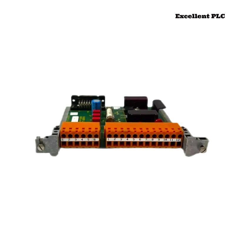
The Honeywell 05701-A-0325 DC Input Card is the primary power distribution module for the Honeywell System 57 Gas Detection Controller. It receives the external 24 VDC power supply, distributes power to the rack backplane, supports optional standby battery operation, and protects the system through reverse polarity protection, fuse protection, and EMI filtering. If the DC Input Card or its associated power circuits develop faults, the entire controller rack may fail to start or experience unstable operation. A systematic troubleshooting procedure helps maintenance engineers identify power-related faults quickly and restore reliable system operation.
Contents
- 1. Understanding DC Input Card Faults
- 2. Common Failure Symptoms
- 3. Typical Causes
- 4. Initial Hardware Inspection
- 5. Electrical Verification
- 6. Diagnostic Analysis
- 7. Recommended Troubleshooting Workflow
- 8. Corrective Actions
- 9. Functional Recovery Verification
- 10. Preventive Maintenance
- 11. Industrial Maintenance Case
- 12. Frequently Asked Questions
Understanding DC Input Card Faults
The 05701-A-0325 supplies regulated DC power to every module installed in the System 57 rack. Problems affecting the incoming 24 VDC supply, terminal wiring, fuse protection, backup battery input, or internal power distribution circuitry can prevent the controller from operating correctly. Before replacing the DC Input Card, engineers should verify the external power source, wiring integrity, and rack connections.
Common Failure Symptoms
- System 57 controller does not power up.
- No LEDs illuminate on installed control cards.
- Intermittent controller shutdowns.
- Backplane voltage is unstable.
- Backup battery fails to operate.
- Repeated fuse failures.
- Power alarm is displayed.
- Random controller resets occur.
Typical Causes
- Loss of external 24 VDC supply.
- Incorrect wiring polarity.
- Loose terminal block connections.
- Blown input fuse.
- Damaged backup battery circuit.
- Poor rack connector contact.
- Excessive electrical noise.
- Overloaded power distribution circuit.
- Internal DC Input Card failure.
Initial Hardware Inspection
- Verify the external 24 VDC power supply.
- Inspect the terminal block connections.
- Check fuse condition.
- Inspect rack connectors.
- Verify backup battery wiring.
- Review controller power indicators.
Electrical Verification
- Measure the input DC voltage.
- Verify polarity at TB1 terminals.
- Measure backplane supply voltage.
- Check fuse continuity.
- Verify backup battery voltage.
- Inspect grounding continuity.
Diagnostic Analysis
| Observed Condition | Possible Diagnosis |
|---|---|
| No controller power | 24 VDC supply failure, blown fuse, or input card fault |
| Backplane voltage unstable | Loose wiring, overloaded supply, or internal power circuit failure |
| Frequent controller reboot | Input voltage fluctuations or poor terminal connections |
| Backup battery unavailable | Battery wiring fault or backup input circuit failure |
| Repeated fuse replacement required | Short circuit, overload, or damaged power module |
Recommended Troubleshooting Workflow
VERIFY EXTERNAL POWER SUPPLY
CHECK INPUT VOLTAGE
INSPECT TERMINAL CONNECTIONS
VERIFY FUSE CONDITION
MEASURE BACKPLANE VOLTAGE
TEST BACKUP BATTERY INPUT
CHECK RACK POWER DISTRIBUTION
CONFIRM NORMAL OPERATION
Corrective Actions
- Restore a stable 24 VDC power supply.
- Correct wiring polarity.
- Tighten loose terminal connections.
- Replace blown fuses with the correct rating.
- Repair damaged backup battery wiring.
- Clean rack connectors.
- Reduce excessive electrical interference.
- Replace the DC Input Card after confirming an internal fault.
Functional Recovery Verification
- Confirm stable rack power distribution.
- Verify normal backplane voltage.
- Check controller startup.
- Verify all control cards power correctly.
- Test standby battery operation.
- Monitor long-term voltage stability.
Preventive Maintenance
- Inspect terminal blocks regularly.
- Measure input voltage periodically.
- Check fuse condition during maintenance.
- Verify battery backup functionality.
- Clean module connectors.
- Review power system performance.
Industrial Maintenance Case
An offshore gas detection system experienced repeated controller shutdowns after brief power interruptions. Engineers inspected the Honeywell 05701-A-0325 DC Input Card and confirmed the module was operating correctly. Further investigation revealed loose input terminals that caused intermittent voltage drops whenever vibration occurred.
After tightening the terminal connections, verifying input voltage stability, testing the backup battery supply, and monitoring backplane voltage:
- The controller powered up normally.
- Unexpected shutdowns were eliminated.
- All control cards operated reliably.
- The gas detection system returned to continuous service.
Frequently Asked Questions
Why does the System 57 controller fail to start?
Common causes include loss of the 24 VDC power supply, blown input fuse, incorrect wiring polarity, loose terminal connections, or an internal DC Input Card fault.
Why is the backplane voltage unstable?
Voltage instability may result from poor wiring connections, overloaded power supplies, electrical interference, damaged connectors, or internal power distribution problems.
When should the 05701-A-0325 DC Input Card be replaced?
The module should only be replaced after confirming that the external power supply, fuse, wiring, backup battery circuit, and rack connectors are operating correctly while the card continues to produce abnormal power distribution or internal faults.
Summary
Effective troubleshooting of the Honeywell 05701-A-0325 DC Input Card requires systematic verification of the 24 VDC power source, wiring integrity, fuse condition, backup battery input, backplane voltage, and rack power distribution. Regular preventive maintenance and periodic electrical inspections help ensure reliable operation of Honeywell System 57 gas detection systems.