 Excellent PLC


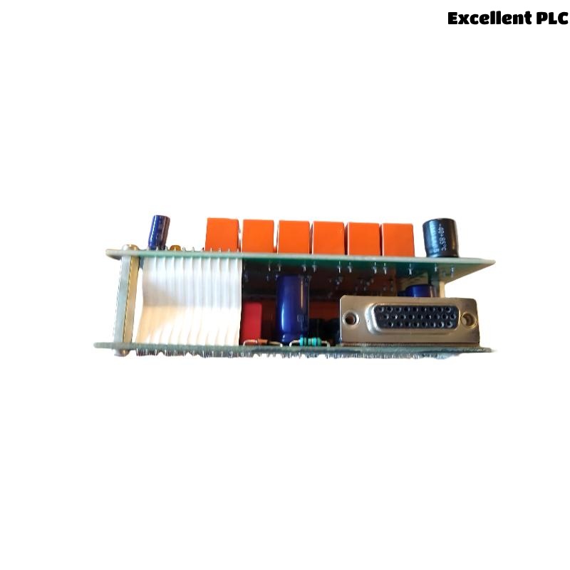
The Honeywell 05704-A-0121 Quad Relay Interface Card is a field interface module used with the Honeywell System 5704 Gas Detection Controller. It connects up to four gas detectors to the Four Channel Control Card while providing four configurable SPCO relay outputs for alarm, fault, inhibit, and master alarm functions. The module also supports analog outputs, detector power distribution, and remote reset inputs. During long-term industrial operation, issues such as relay failures, detector communication errors, wiring faults, analog output abnormalities, or configuration problems may affect system reliability. A systematic troubleshooting procedure enables maintenance personnel to quickly identify the root cause and restore safe operation.
Contents
- 1. Understanding Interface Card Faults
- 2. Common Failure Symptoms
- 3. Typical Causes
- 4. Initial Hardware Inspection
- 5. Electrical Verification
- 6. Diagnostic Analysis
- 7. Recommended Troubleshooting Workflow
- 8. Corrective Actions
- 9. Functional Recovery Verification
- 10. Preventive Maintenance
- 11. Industrial Maintenance Case
- 12. Frequently Asked Questions
Understanding Interface Card Faults
The Honeywell 05704-A-0121 serves as the connection point between field gas detectors and the System 5704 controller. It distributes detector power, processes field wiring, and controls configurable relay outputs. Faults may be caused by damaged relay contacts, loose terminal connections, incorrect relay assignments, analog output failures, detector wiring problems, or communication errors between the interface card and the Four Channel Control Card.
Common Failure Symptoms
- One or more detector channels are not recognized.
- Alarm relay fails to activate.
- Fault relay remains continuously energized.
- Analog output is missing or unstable.
- Remote reset function does not operate.
- False gas alarms occur.
- Relay contacts chatter during switching.
- Controller reports interface communication errors.
Typical Causes
- Loose terminal wiring.
- Damaged relay contacts.
- Incorrect relay configuration.
- Sensor wiring short circuit or open circuit.
- Power supply abnormalities.
- Poor connector contact.
- Electrical interference.
- Internal interface card failure.
Initial Hardware Inspection
- Verify controller power supply.
- Inspect module connectors.
- Check detector wiring terminals.
- Inspect relay output terminals.
- Verify analog output wiring.
- Review controller diagnostic indicators.
Electrical Verification
- Measure detector supply voltage.
- Verify relay contact continuity.
- Measure analog output signal.
- Inspect field cable insulation.
- Verify protective grounding.
- Measure relay output voltage where applicable.
Diagnostic Analysis
| Observed Condition | Possible Diagnosis |
|---|---|
| No detector input | Field wiring fault, power loss, or interface card failure |
| Relay output inactive | Relay configuration error, damaged contacts, or controller communication fault |
| Analog output unstable | Poor wiring, electrical interference, or analog circuit failure |
| False alarms | Detector instability, wiring noise, or incorrect configuration |
| Remote reset unavailable | Incorrect wiring or reset circuit failure |
Recommended Troubleshooting Workflow
VERIFY SYSTEM POWER
CHECK INTERFACE CARD STATUS
INSPECT FIELD WIRING
VERIFY DETECTOR POWER
TEST RELAY OUTPUTS
CHECK ANALOG OUTPUTS
VERIFY CONFIGURATION
CONFIRM NORMAL OPERATION
Corrective Actions
- Tighten loose terminal connections.
- Repair damaged field wiring.
- Replace defective relay contacts if applicable.
- Correct relay configuration parameters.
- Clean connector contacts.
- Repair analog output wiring.
- Verify communication with the Four Channel Control Card.
- Replace the interface card after confirming internal hardware failure.
Functional Recovery Verification
- Verify all four detector channels operate normally.
- Test each configured relay output.
- Verify analog output accuracy.
- Test remote reset functionality.
- Confirm alarm response for each channel.
- Monitor long-term communication stability.
Preventive Maintenance
- Inspect field wiring periodically.
- Verify relay operation during scheduled maintenance.
- Clean module connectors.
- Check analog outputs regularly.
- Verify terminal tightness.
- Perform routine detector functional testing.
Industrial Maintenance Case
A petrochemical plant reported that Channel 3 of a Honeywell System 5704 controller failed to activate its external alarm relay during gas detector testing. Engineers verified that the detector and controller were functioning correctly and traced the fault to a loose relay output terminal on the Honeywell 05704-A-0121 Quad Relay Interface Card.
After tightening the terminal connections, verifying relay configuration, testing analog outputs, and repeating alarm simulations:
- All four detector channels communicated normally.
- Each relay output responded correctly.
- Analog output signals remained stable.
- The gas detection system successfully passed functional acceptance testing.
Frequently Asked Questions
Why does one detector channel fail to respond?
The most common causes include loose field wiring, loss of detector power, damaged terminal connections, or an interface card fault affecting the channel.
Why is the relay output not operating?
This may result from incorrect relay configuration, damaged relay contacts, communication problems with the Four Channel Control Card, or wiring faults between the interface card and external equipment.
When should the Honeywell 05704-A-0121 Interface Card be replaced?
The module should be replaced only after confirming that the controller, detector wiring, power supply, relay configuration, analog output circuits, and external devices are functioning correctly while the interface card continues to exhibit internal hardware or communication faults.
Summary
Effective troubleshooting of the Honeywell 05704-A-0121 Quad Relay Interface Card requires systematic inspection of detector wiring, relay outputs, analog signals, communication status, connector integrity, and configuration parameters. Routine preventive maintenance and scheduled functional testing help ensure reliable gas detection and alarm operation in Honeywell System 5704 safety systems.