

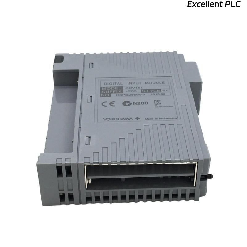
Yokogawa ADV151-D132 Digital Input Module faults are typically caused by signal loss, wiring defects, grounding issues, unstable 24 VDC supplies, or configuration inconsistencies rather than actual hardware failure. Effective Troubleshooting requires engineers to analyze the entire signal path before replacing the module. The ADV151 family supports isolated 24 VDC digital input monitoring and provides diagnostic functions for industrial automation applications.
Contents
- ADV151-D132 Digital Input Module Fault Symptoms
- Typical Failure Patterns
- Common Causes of ADV151-D132 Input Faults
- Fault Diagnosis Logic
- Field Signal Investigation
- Input Wiring Fault Analysis
- Voltage and Power Diagnostics
- System Configuration Troubleshooting
- ADV151-D132 Diagnostic Indicators
- Practical Troubleshooting Workflow
- Recovery and Repair Actions
- Repair Validation Procedure
- Preventive Maintenance Practices
- Real Fault Diagnosis Case
- FAQ
ADV151-D132 Digital Input Module Fault Symptoms
- Input point remains OFF
- Unexpected status changes
- Intermittent alarms
- Incorrect equipment indication
- Control sequence interruption
- Event history inconsistencies
Typical Failure Patterns
Most ADV151-D132 issues appear as unstable input signals rather than complete module failures. Engineers often observe channels changing state unexpectedly during plant operation.
- Random signal dropout
- Noise-induced transitions
- Partial channel failures
- False alarm generation
Common Causes of ADV151-D132 Input Faults
- Loose field terminals
- Broken signal wiring
- Power supply fluctuations
- Poor grounding
- Incorrect polarity
- Electrical interference
- Database configuration errors
Fault Diagnosis Logic
Experienced engineers avoid replacing the Digital Input Module immediately. Instead, they verify whether the field device, wiring path, terminal block, module channel, and controller database all agree with the actual process condition.
Field Signal Investigation
- Measure signal voltage
- Inspect switch operation
- Verify relay contacts
- Check sensor outputs
Input Wiring Fault Analysis
- Inspect terminal tightness
- Verify cable continuity
- Review wiring drawings
- Check junction boxes
Voltage and Power Diagnostics
| Measured Value | Diagnostic Result |
|---|---|
| 0 VDC | Open circuit or failed signal source |
| 24 VDC Stable | Signal available |
| 8–15 VDC | Loose connection or voltage drop |
| Fluctuating Signal | Noise or grounding issue |
System Configuration Troubleshooting
- Verify tag database
- Check channel allocation
- Review logic references
- Validate controller synchronization
- Inspect alarm configuration
ADV151-D132 Diagnostic Indicators
- Status LED monitoring
- Input activity analysis
- Diagnostic alarm review
- Communication health verification
Practical Troubleshooting Workflow
CHECK FIELD DEVICE
MEASURE INPUT VOLTAGE
VERIFY WIRING CONTINUITY
CHECK TERMINAL BLOCKS
REVIEW SYSTEM CONFIGURATION
MONITOR INPUT STATUS
IDENTIFY ROOT CAUSE
APPLY CORRECTIVE ACTION
Recovery and Repair Actions
- Repair damaged cables
- Retighten terminals
- Replace faulty sensors
- Correct configuration errors
- Improve grounding systems
- Replace module if necessary
Repair Validation Procedure
- Operate field devices repeatedly
- Verify status changes
- Monitor alarm behavior
- Check event logs
- Confirm process stability
Preventive Maintenance Practices
- Routine voltage checks
- Scheduled terminal inspections
- Grounding verification
- Configuration backup management
Real Fault Diagnosis Case
A power generation facility reported repeated ADV151-D132 alarms on turbine auxiliary status signals.
- Input Voltage: 23.9 VDC
- Alarm Frequency: 25 events/hour
- Module Diagnostics: Normal
- Controller Status: Healthy
The maintenance team initially prepared a replacement Digital Input Module. During Fault Diagnosis, engineers observed that signal voltage dropped to 11.4 VDC whenever nearby motor starters operated.
Further investigation identified a deteriorated grounding connection within the marshalling cabinet.
After grounding repairs:
- Signal voltage stabilized at 24 VDC
- Alarm frequency dropped to zero
- Input transitions became stable
- No module replacement was required
We observed that grounding failures can closely imitate Digital Input Module faults and often lead to unnecessary hardware replacement.
ADV151-D132 Fault Diagnosis FAQ
Does an inactive channel always indicate module failure?
No. Most faults originate from field wiring, signal sources, grounding systems, or configuration issues.
What should engineers check first during Troubleshooting?
Verify signal voltage, field device operation, wiring continuity, and System Configuration before evaluating hardware.
Can electrical noise affect Digital Input Module performance?
Yes. Poor grounding and electromagnetic interference can cause false transitions and intermittent alarms.
Summary: Effective ADV151-D132 Troubleshooting depends on structured Fault Diagnosis, signal verification, wiring analysis, voltage measurements, and System Configuration review before module replacement is considered.