

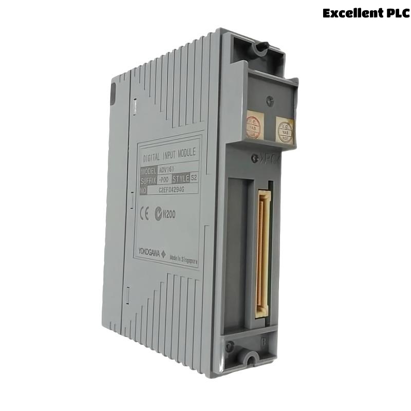
Yokogawa ADV161 Digital Input Module installation failures are typically caused by incorrect 24 VDC wiring, improper channel allocation, or incomplete System Configuration rather than module hardware defects. Following a structured Installation Guide can significantly reduce commissioning time and improve long-term signal reliability. The ADV161 is commonly deployed as a 64-channel Digital Input Module for monitoring field status signals within Yokogawa FIO and CENTUM systems.
Contents
- ADV161 Digital Input Module Overview
- ADV161 Digital Input Module Specifications
- ADV161 Engineering Preparation
- ADV161 Cabinet Installation Requirements
- ADV161 Hardware Inspection
- ADV161 Power and Signal Verification
- ADV161 Module Installation Procedure
- ADV161 Wiring Installation Guide
- ADV161 Grounding and Shielding Design
- ADV161 Channel Allocation Strategy
- ADV161 System Configuration Setup
- ADV161 Input Signal Testing
- ADV161 Commissioning Validation
- ADV161 Operational Optimization
- ADV161 Maintenance Recommendations
- Real Field Commissioning Case
- FAQ
ADV161 Digital Input Module Overview
The Yokogawa ADV161 Digital Input Module acquires digital ON/OFF signals from process equipment including limit switches, motor starters, emergency shutdown contacts, valve feedback devices, and relay outputs. The module supports 64 input channels and 24 VDC signal processing.
ADV161 Digital Input Module Specifications
- 64 digital input channels
- 24 VDC sink/source input
- Input ON voltage: 20–26.4 VDC
- Input OFF voltage: 5 VDC or below
- Fast response characteristics
- Channel isolation support
These specifications make the ADV161 suitable for large-scale process plants requiring high-density digital signal acquisition.
ADV161 Engineering Preparation
- Review I/O allocation drawings
- Verify loop diagrams
- Confirm terminal schedules
- Prepare commissioning checklists
- Verify cabinet space availability
ADV161 Cabinet Installation Requirements
- Stable environmental temperature
- Proper ventilation
- Reliable grounding network
- EMI-controlled cable routing
- Adequate maintenance access
ADV161 Hardware Inspection
- Verify model identification
- Inspect connectors
- Check terminal integrity
- Review shipment condition
- Inspect module indicators
ADV161 Power and Signal Verification
Before installation, verify field signal voltage levels. Most commissioning delays occur because field devices do not provide the expected 24 VDC signal state.
- Measure input voltage
- Verify common returns
- Inspect fuse condition
- Check cable continuity
- Validate field contacts
ADV161 Module Installation Procedure
- Isolate cabinet power.
- Insert the ADV161 module into the designated slot.
- Secure retaining mechanisms.
- Connect field termination cables.
- Verify module seating.
- Restore system power.
ADV161 Wiring Installation Guide
The most effective way to avoid future Troubleshooting is to implement disciplined wiring practices during Setup.
- Separate power and signal wiring
- Apply cable identification labels
- Avoid shared return conductors
- Verify terminal assignments
- Perform continuity testing
ADV161 Grounding and Shielding Design
- Use single-point grounding
- Terminate shields correctly
- Avoid ground loops
- Verify cabinet bonding
- Inspect earth continuity
ADV161 Channel Allocation Strategy
Field experience shows grouping related process signals together simplifies maintenance and Fault Diagnosis activities after startup.
- Pump status signals
- Valve feedback signals
- Interlock contacts
- Shutdown inputs
- Utility monitoring signals
ADV161 System Configuration Setup
SCAN MODULE
VERIFY NODE STATUS
ASSIGN INPUT CHANNELS
CONFIGURE TAG DATABASE
DOWNLOAD CONFIGURATION
SAVE PROJECT
ACTIVATE INPUTS
ADV161 Input Signal Testing
- Toggle field contacts
- Verify channel transitions
- Check alarm generation
- Validate event logs
- Confirm operator graphics
ADV161 Commissioning Validation
Commissioning should use actual field devices instead of simulation whenever possible. Real process operation exposes hidden wiring defects that simulations often miss.
ADV161 Operational Optimization
- Improve cable segregation
- Reduce electrical noise
- Optimize grounding quality
- Improve signal documentation
ADV161 Maintenance Recommendations
- Inspect terminals annually
- Review diagnostics monthly
- Verify grounding integrity
- Maintain project backups
Real Field Commissioning Case
During startup of a petrochemical utility system, operators reported that 16 digital feedback signals connected to an ADV161 remained inactive.
- Measured Voltage: 24.1 VDC
- Module Status: Healthy
- Communication Status: Normal
- Affected Channels: 16
We observed that every affected channel belonged to a single marshalling cabinet. Investigation revealed a disconnected common return conductor introduced during cabinet modification.
After reconnecting the return path:
- All 16 channels became operational
- Operator graphics updated correctly
- Alarm functions recovered
- Startup activities resumed
ADV161 Installation Guide FAQ
What voltage signals are supported by the ADV161 Digital Input Module?
The module is designed for 24 VDC digital input signals and supports sink/source configurations.
How many channels does the ADV161 provide?
The ADV161 supports 64 digital input channels for high-density applications.
What causes most installation problems?
Incorrect wiring, grounding deficiencies, and System Configuration errors are more common than module hardware failures.
Summary: Reliable ADV161 Installation, Setup, and Commissioning depend on accurate wiring, proper grounding, disciplined System Configuration, and comprehensive field validation.