

Yokogawa ADV551 Digital Output Module output failures are more likely to be caused by field wiring defects, power supply abnormalities, damaged output loads, or incorrect System Configuration than by module hardware failure. A systematic Troubleshooting process allows engineers to isolate the real fault quickly, minimize downtime, and avoid unnecessary module replacement.
Contents
- 1. ADV551 Digital Output Module Fault Symptoms
- 2. Fault Diagnosis Strategy
- 3. Common Causes of ADV551 Output Failure
- 4. Controller Command Verification
- 5. Output Voltage Analysis
- 6. Output Load Inspection
- 7. Wiring Fault Troubleshooting
- 8. External Power Supply Diagnosis
- 9. ADV551 System Configuration Verification
- 10. Diagnostic Indicator Review
- 11. Practical Fault Diagnosis Workflow
- 12. Repair and Recovery Actions
- 13. Post-Repair Verification
- 14. Preventive Maintenance Practices
- 15. Real Field Fault Diagnosis Case
- 16. FAQ
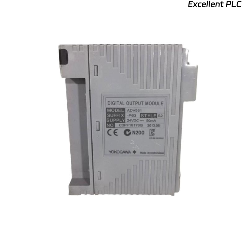
ADV551 Digital Output Module Fault Symptoms
Output-related failures often appear gradually rather than as complete module failures. Recognizing the symptoms early can significantly shorten the Fault Diagnosis process.
- Output channel remains OFF after command execution
- Relay operates intermittently
- Solenoid valve does not respond
- Output LED changes state but field device remains inactive
- Unexpected shutdown or interlock activation
- Repeated output alarms during operation
Fault Diagnosis Strategy
Experienced field engineers rarely replace the Digital Output Module first. Instead, they verify whether the controller is issuing a valid command, confirm electrical output at the terminal, inspect field wiring, and finally evaluate the connected load. This sequence prevents unnecessary hardware replacement and reduces maintenance costs.
Common Causes of ADV551 Output Failure
- Loose terminal connections
- Incorrect field wiring
- Blown protection fuse
- Shorted relay coil
- Power supply instability
- Incorrect output mapping
- Damaged terminal block
- Grounding problems
Controller Command Verification
Before inspecting the module, confirm that the controller logic is actually issuing the output command.
- Check control sequence status
- Verify interlock conditions
- Review permissive signals
- Monitor output tag status
- Confirm command execution time
Output Voltage Analysis
| Measured Output | Possible Diagnosis |
|---|---|
| 24 VDC Stable | Module output operating normally |
| 0 VDC | No controller output or open circuit |
| 8–15 VDC | Output overloaded or voltage drop |
| Rapid fluctuation | Loose wiring or unstable power supply |
Measurements should always be taken while the output channel is under normal operating load rather than with the field cable disconnected.
Output Load Inspection
Field devices often become the real source of output failures.
- Measure relay coil resistance
- Inspect solenoid valve current
- Check contactor operation
- Verify indicator lamp integrity
- Inspect external protection devices
Wiring Fault Troubleshooting
Incorrect wiring accounts for a large percentage of commissioning and maintenance problems involving Digital Output Modules.
- Inspect terminal torque
- Check cable continuity
- Verify polarity
- Inspect junction boxes
- Confirm output common wiring
- Check cable identification
External Power Supply Diagnosis
The Digital Output Module may operate normally while external power supplies prevent field equipment from responding.
- Measure supply voltage under load
- Inspect DC power distribution
- Check fuse holders
- Verify common return voltage
- Monitor voltage fluctuations during startup
ADV551 System Configuration Verification
Incorrect configuration may cause the controller to energize the wrong output channel even though the hardware is functioning correctly.
- Review channel allocation
- Verify tag mapping
- Confirm controller database
- Check interlock configuration
- Validate project download status
Diagnostic Indicator Review
- Inspect module LEDs
- Review controller event history
- Check communication status
- Monitor diagnostic alarms
- Verify rack health information
Practical Fault Diagnosis Workflow
VERIFY OUTPUT COMMAND
CHECK MODULE LED
MEASURE OUTPUT VOLTAGE
VERIFY EXTERNAL POWER
INSPECT FIELD WIRING
TEST OUTPUT LOAD
CHECK SYSTEM CONFIGURATION
IDENTIFY ROOT CAUSE
VERIFY NORMAL OPERATION
This workflow follows the actual signal path and helps eliminate unnecessary troubleshooting steps.
Repair and Recovery Actions
- Replace damaged field wiring
- Repair loose terminal connections
- Replace defective relay coils
- Correct output database mapping
- Repair external power circuits
- Replace the module only after all external causes have been eliminated
Post-Repair Verification
- Execute multiple output commands
- Observe field device response
- Confirm operator graphics
- Verify alarm reset functions
- Monitor operation for at least one production cycle
Preventive Maintenance Practices
Routine inspections significantly reduce unexpected digital output failures.
- Inspect output terminals every six months
- Measure power supply voltage regularly
- Verify relay operating current
- Check cabinet grounding annually
- Maintain updated configuration backups
Real Field Fault Diagnosis Case
During maintenance at a petrochemical plant, operators reported that several process valves failed to respond to controller commands issued through an ADV551 Digital Output Module.
Initial observations suggested a module failure because the valves remained stationary even though the HMI displayed active output commands.
Rather than replacing the module immediately, engineers followed a structured Fault Diagnosis process.
- Controller Command Status: Normal
- Module LED Status: ON
- Measured Output Voltage: 24.2 VDC
- Field Device Response: No Action
Further inspection identified excessive resistance in a corroded terminal block located inside the field marshalling cabinet. The voltage measured correctly at the module but dropped below 10 VDC at the valve terminal during operation.
After replacing the damaged terminal block:
- Output voltage at the valve recovered to 24 VDC.
- Valve response became immediate.
- No additional output alarms occurred.
- The ADV551 module continued operating without replacement.
This case illustrates an important field lesson: voltage should always be measured at both the module and the field device to locate hidden wiring losses.
ADV551 Fault Diagnosis FAQ
Does a lit output LED guarantee that the field device is operating?
No. The controller may be issuing a correct output command while external wiring, power supplies, or the connected load prevents the device from responding.
What is the first measurement during ADV551 Troubleshooting?
Verify the output voltage at the module terminal and then compare it with the voltage measured directly at the field device under load.
Should the Digital Output Module be replaced immediately when an output channel fails?
No. Most output failures are caused by wiring defects, blown fuses, damaged loads, or configuration errors. Hardware replacement should be the final step after completing a structured Fault Diagnosis.
Summary: Reliable ADV551 Troubleshooting combines controller verification, electrical measurement, field load inspection, System Configuration validation, and practical engineering analysis to identify the real cause of output failures quickly and accurately.