

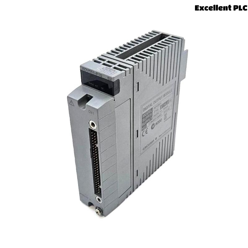
The Yokogawa ADV561 Digital Output Module is a high-density 64-channel transistor output module used in Yokogawa FIO systems. When output failures occur, they are most commonly caused by field wiring issues, external power instability, overloaded circuits, or configuration errors rather than internal module defects. A structured Troubleshooting approach helps engineers quickly isolate the root cause, reduce downtime, and avoid unnecessary module replacement.
Contents
- 1. Understanding ADV561 Output Failures
- 2. Common Fault Symptoms
- 3. Typical Causes of Output Failure
- 4. Controller Logic Verification
- 5. Module Status Inspection
- 6. Output Voltage Measurement
- 7. Field Load Inspection
- 8. Wiring and Terminal Diagnosis
- 9. External Power Supply Check
- 10. System Configuration Review
- 11. Recommended Troubleshooting Workflow
- 12. Corrective Actions
- 13. Functional Recovery Verification
- 14. Preventive Maintenance
- 15. Real Field Case Study
- 16. FAQ
Understanding ADV561 Output Failures
Most ADV561 output issues are not caused by internal module failure. Instead, they originate from field-side problems such as wiring degradation, voltage drop, faulty actuators, or incorrect configuration in the control system.
Because of the high channel density (64 outputs), a single wiring or power issue can affect multiple field devices simultaneously, making systematic diagnosis essential.
Common Fault Symptoms
- Output LED ON but field device not operating
- Multiple channels failing simultaneously
- Intermittent relay or solenoid operation
- Valve not responding to command
- Motor starter does not energize
- Unexpected shutdown or alarm output failure
- Reduced output voltage under load
Typical Causes of Output Failure
- Loose terminal connections in marshalling cabinet
- Incorrect field wiring or reversed polarity
- External fuse blown
- High resistance in common return line
- Power supply voltage drop
- Shorted solenoid or relay coil
- Incorrect channel mapping in configuration
- Ground loop interference
Controller Logic Verification
Before investigating hardware, confirm that the controller is actually issuing the output command.
- Check sequence logic execution
- Verify interlock conditions
- Confirm operator command status
- Inspect output tag values
- Review control program state
Module Status Inspection
- Check RUN LED status
- Inspect channel LEDs
- Review system diagnostic alarms
- Verify node communication status
- Confirm module seating in rack
Output Voltage Measurement
| Measured Condition | Interpretation |
|---|---|
| 24 VDC stable | Output circuit normal |
| 0 VDC | No command or open circuit |
| 8–15 VDC under load | High resistance or overloaded circuit |
| Fluctuating voltage | Loose wiring or unstable power supply |
Measurements must be taken under load conditions at both module terminals and field devices to identify hidden voltage drops.
Field Load Inspection
Many ADV561 faults originate from field devices rather than the module itself.
- Measure relay coil resistance
- Check solenoid valve current draw
- Inspect contactor operation
- Verify suppression diodes
- Inspect actuator wiring integrity
Wiring and Terminal Diagnosis
- Inspect terminal tightening
- Verify cable continuity
- Check conductor polarity
- Inspect marshalling cabinet wiring
- Inspect junction box connections
- Verify common return wiring path
External Power Supply Check
A stable 24 VDC supply is essential for correct operation of all output channels.
- Measure supply voltage under load
- Inspect DC distribution system
- Check fuse integrity
- Verify common negative bus
- Monitor voltage during switching events
System Configuration Review
- Verify channel mapping
- Review controller database
- Confirm project download status
- Check tag assignments
- Validate logic references
Recommended Troubleshooting Workflow
VERIFY CONTROLLER COMMAND
CHECK MODULE STATUS
MEASURE OUTPUT VOLTAGE
VERIFY FIELD POWER
INSPECT WIRING
CHECK FIELD LOAD
VERIFY CONFIGURATION
IDENTIFY ROOT CAUSE
PERFORM FUNCTION TEST
This structured workflow follows the full signal path from controller to field device, ensuring accurate fault isolation.
Corrective Actions
- Repair damaged wiring or connectors
- Replace corroded terminal blocks
- Fix incorrect configuration settings
- Replace faulty relay or solenoid loads
- Repair unstable DC power supply circuits
- Replace ADV561 module only after all external causes are eliminated
Functional Recovery Verification
- Repeat output command testing
- Verify relay or valve response
- Monitor system diagnostics
- Check continuous operation stability
- Validate all affected channels
Preventive Maintenance
Preventive maintenance significantly reduces unexpected output failures in high-density modules like ADV561.
- Inspect terminals every 6 months
- Measure output voltage periodically
- Check grounding integrity annually
- Review diagnostic logs regularly
- Maintain backup configuration files
Real Field Case Study
In a chemical processing plant, multiple cooling fan contactors controlled by an ADV561 module failed to energize during startup.
All controller commands were normal, and the module indicated correct output status. However, voltage measured at field devices dropped below 10 VDC when energized.
After systematic inspection, engineers identified a deteriorated common return conductor in the marshalling cabinet causing high resistance and severe voltage drop across multiple channels.
After replacing the damaged wiring:
- All contactors energized successfully
- Field voltage returned to 24 VDC
- No module replacement was required
- System resumed stable operation
FAQ
Why does ADV561 output LED turn ON but field device remains OFF?
This typically indicates external wiring faults, insufficient power supply, or failed field devices rather than module failure.
What is the first step in troubleshooting ADV561?
Verify controller command status and measure output voltage under load conditions at both module and field device.
When should the ADV561 module be replaced?
Only after confirming controller logic, wiring integrity, field devices, configuration, and power supply are all functioning correctly.
Summary: Effective ADV561 troubleshooting requires a structured diagnostic approach combining controller verification, electrical measurement, wiring inspection, load evaluation, and configuration analysis to ensure accurate fault isolation and reliable system recovery.