

The Yokogawa AE4D-05 Terminal Board is a field wiring interface designed for Yokogawa FIO systems. It provides secure termination of field signals between analog I/O modules and external instrumentation. Supporting 16 channels in both single and dual-redundant configurations, the AE4D-05 simplifies cabinet wiring, improves signal organization, and enhances long-term maintenance efficiency. Proper installation, wiring, grounding, and commissioning are essential for maintaining reliable signal transmission and system performance.
Contents
- 1. AE4D-05 Terminal Board Overview
- 2. Technical Features
- 3. Typical Industrial Applications
- 4. Installation Planning
- 5. Hardware Inspection
- 6. Installation Environment
- 7. Terminal Board Mounting Procedure
- 8. Field Wiring Installation
- 9. Grounding and Shielding
- 10. Connection to I/O Modules
- 11. Wiring Verification
- 12. Commissioning Procedure
- 13. Functional Testing
- 14. Preventive Maintenance
- 15. Practical Installation Case
- 16. Frequently Asked Questions
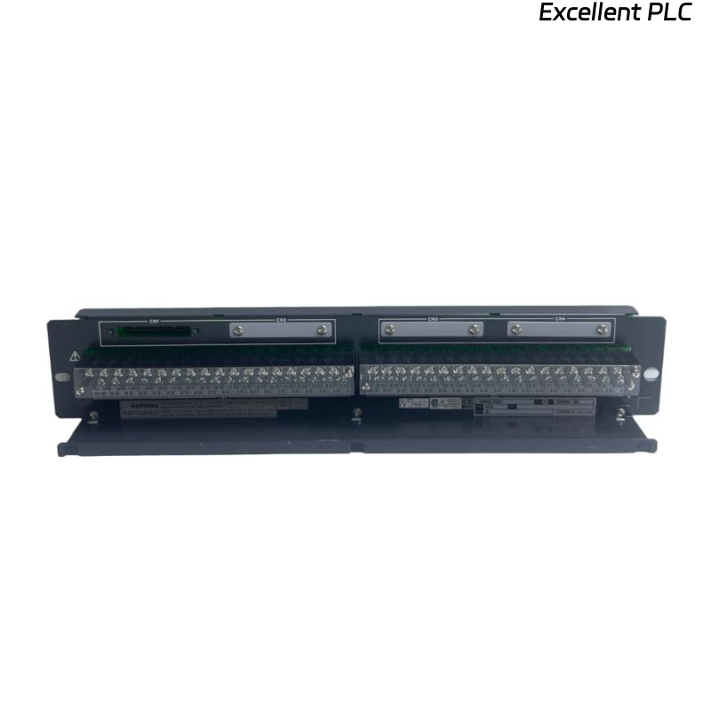
AE4D-05 Terminal Board Overview
The AE4D-05 is a 16-channel terminal board for analog signal termination in Yokogawa FIO systems. It supports both single and dual-redundant I/O module configurations, connects to analog modules through a KS1 connection cable, and provides screw terminals for secure field wiring. The basic “-05” version is supplied without a surge absorber and is intended for standard industrial installations without explosion protection. :contentReference[oaicite:0]{index=0}
Technical Features
- 16-channel analog terminal board
- Supports single and dual-redundant modules
- KS1 connection cable interface
- Screw terminal connections
- Compact cabinet installation
- Designed for Yokogawa FIO systems
Typical Industrial Applications
- Process control cabinets
- Chemical plants
- Oil and gas facilities
- Power generation systems
- Water treatment plants
- Industrial automation systems
Installation Planning
Careful engineering preparation reduces installation errors and simplifies commissioning.
- Review wiring diagrams
- Verify channel assignments
- Confirm cable schedules
- Prepare terminal labels
- Inspect cabinet layout
Hardware Inspection
- Verify part number
- Inspect terminal screws
- Check insulation condition
- Inspect mounting hardware
- Verify KS1 connector integrity
Installation Environment
- Maintain adequate ventilation
- Avoid excessive humidity
- Protect from vibration
- Separate signal and power wiring
- Maintain clean cabinet conditions
Terminal Board Mounting Procedure
- Switch OFF cabinet power.
- Install the AE4D-05 on the designated mounting rail or panel.
- Secure all mounting hardware.
- Verify mechanical alignment.
- Connect the KS1 interface cable.
- Inspect connector engagement.
Field Wiring Installation
Correct field wiring ensures stable analog signal transmission and simplifies future maintenance.
- Label every field cable
- Separate signal wiring from power cables
- Verify cable continuity
- Inspect insulation resistance
- Confirm terminal tightening torque
Grounding and Shielding
- Use single-point grounding
- Terminate cable shields correctly
- Avoid ground loops
- Verify cabinet bonding
- Inspect earth continuity
Connection to I/O Modules
INSTALL TERMINAL BOARD
CONNECT KS1 CABLE
VERIFY CONNECTOR LOCK
CONNECT FIELD SIGNALS
CHECK TERMINAL NUMBERS
VERIFY CHANNEL ASSIGNMENTS
Wiring Verification
- Check terminal identification
- Verify channel continuity
- Measure insulation resistance
- Inspect cable routing
- Confirm polarity where applicable
Commissioning Procedure
- Power the control cabinet
- Verify module communication
- Check analog signal values
- Inspect controller diagnostics
- Record commissioning results
Functional Testing
- Verify all 16 signal channels
- Check terminal continuity
- Confirm stable analog readings
- Monitor controller diagnostics
- Validate complete signal transmission
Preventive Maintenance
- Inspect terminal screws every six months
- Check cable insulation periodically
- Clean cabinet interior
- Verify grounding annually
- Maintain updated wiring documentation
Practical Installation Case
During commissioning of a refinery expansion project, engineers observed unstable analog input readings from several pressure transmitters connected through an AE4D-05 terminal board.
Inspection confirmed that the I/O module and controller were operating normally. Further investigation revealed that multiple terminal screws on the terminal board had not been tightened to the specified torque after field wiring installation.
After retightening the affected terminals and repeating the commissioning tests:
- Analog signal values became stable.
- Controller diagnostics showed no communication alarms.
- Signal noise disappeared.
- The complete I/O cabinet entered normal operation.
Frequently Asked Questions
What is the primary function of the AE4D-05?
The AE4D-05 provides a 16-channel analog terminal interface between field wiring and Yokogawa analog I/O modules, supporting both single and dual-redundant module configurations. :contentReference[oaicite:1]{index=1}
Which connection cable does the AE4D-05 use?
The terminal board connects to compatible Yokogawa analog I/O modules using the KS1 connection cable. :contentReference[oaicite:2]{index=2}
Does the “-05” version include surge protection?
No. The “-05” basic version is supplied without an integrated surge absorber and is intended for standard industrial installations. :contentReference[oaicite:3]{index=3}
Summary: Proper installation of the Yokogawa AE4D-05 Terminal Board requires accurate mounting, organized field wiring, reliable grounding, secure KS1 cable connections, and comprehensive commissioning to ensure stable analog signal transmission and dependable long-term operation.