

The Yokogawa ADV859 Digital I/O Module is a compact hybrid module that integrates 16 isolated digital input channels and 16 isolated transistor digital output channels into a single unit. Designed for Yokogawa CENTUM-ST2 compatible systems, the ADV859 supports both contact and voltage inputs while providing reliable transistor outputs for industrial automation. Proper installation, wiring, setup, and commissioning ensure dependable field operation, reduce maintenance requirements, and improve long-term system reliability.
Contents
- 1. ADV859 Digital I/O Module Overview
- 2. Technical Features
- 3. Typical Industrial Applications
- 4. Installation Planning
- 5. Hardware Inspection
- 6. Installation Environment
- 7. Power Supply Verification
- 8. Module Installation Procedure
- 9. ADV859 Wiring Installation Guide
- 10. Grounding and Shielding
- 11. Controller Configuration
- 12. Commissioning Procedure
- 13. Functional Verification
- 14. Preventive Maintenance
- 15. Practical Commissioning Case
- 16. Frequently Asked Questions
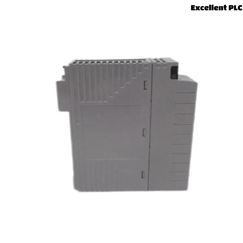
ADV859 Digital I/O Module Overview
The ADV859 combines 16 isolated digital inputs and 16 isolated transistor outputs within one module, making it suitable for applications that require both monitoring and control using minimal cabinet space. The input section accepts dry contact or voltage signals, while the output section provides transistor outputs rated for up to 30 VDC and 100 mA per channel. The module also supports pulse-width and time-proportional output functions and connects externally through a dedicated KS2 cable. It is designed for Yokogawa CENTUM-ST2 compatible systems.
Technical Features
- 16 isolated digital input channels
- 16 isolated transistor output channels
- Support for contact and voltage inputs
- 30 VDC transistor outputs
- Pulse-width and time-proportional output functions
- Dedicated KS2 cable connection
Typical Industrial Applications
- Valve monitoring and control
- Motor starter circuits
- Relay interface panels
- Pump sequencing systems
- Packaging equipment
- Process skid automation
Installation Planning
Engineering verification should be completed before installation begins to ensure that every field signal matches the approved I/O assignment.
- Review loop diagrams
- Verify terminal schedules
- Confirm cable routing
- Prepare commissioning records
- Inspect cabinet layout
Hardware Inspection
- Verify module model number
- Inspect housing condition
- Check connectors and terminals
- Inspect locking mechanism
- Verify dedicated cable condition
Installation Environment
- Maintain cabinet ventilation
- Avoid excessive humidity
- Reduce vibration exposure
- Separate signal and power wiring
- Maintain reliable cabinet grounding
Power Supply Verification
- Measure 24 VDC supply voltage
- Verify correct polarity
- Inspect protective fuses
- Confirm voltage stability
- Verify common return wiring
Module Installation Procedure
- Switch OFF cabinet power.
- Insert the ADV859 into the designated ST2 slot.
- Secure the retaining mechanism.
- Connect the KS2 dedicated cable.
- Inspect connector engagement.
- Restore cabinet power.
ADV859 Wiring Installation Guide
Proper field wiring minimizes electrical interference and improves long-term maintenance efficiency.
- Separate signal cables from AC power wiring
- Label every input and output channel
- Verify cable continuity
- Inspect insulation resistance
- Confirm terminal tightening torque
Grounding and Shielding
- Use single-point grounding
- Terminate cable shields correctly
- Avoid ground loops
- Verify cabinet bonding
- Inspect grounding continuity
Controller Configuration
SCAN I/O MODULE
VERIFY NODE STATUS
ASSIGN INPUT CHANNELS
ASSIGN OUTPUT CHANNELS
MAP PROCESS TAGS
DOWNLOAD CONFIGURATION
SAVE DATABASE
ENABLE I/O
Commissioning Procedure
- Verify digital input status changes
- Execute output switching tests
- Measure field voltage
- Observe connected equipment
- Record commissioning results
Functional Verification
- Confirm all digital inputs
- Verify all digital outputs
- Review controller diagnostics
- Inspect communication status
- Validate complete I/O functionality
Preventive Maintenance
- Inspect field terminals every six months
- Verify power supplies periodically
- Review diagnostic history
- Inspect grounding annually
- Maintain updated engineering backups
Practical Commissioning Case
During commissioning of a chemical dosing skid, engineers observed that all digital input signals updated correctly, while several digital outputs failed to operate connected solenoid valves.
Controller diagnostics confirmed normal communication with the ADV859 module. Electrical measurements showed that the digital output section lacked an external 24 VDC supply due to an incorrectly wired terminal block installed during cabinet assembly.
After correcting the wiring:
- All 16 digital outputs operated normally.
- Input monitoring remained stable.
- No controller alarms occurred.
- The complete skid was commissioned successfully without replacing the module.
Frequently Asked Questions
What I/O configuration does the ADV859 provide?
The ADV859 combines 16 isolated digital input channels and 16 isolated transistor digital output channels within one compact module, making it suitable for mixed monitoring and control applications. :contentReference[oaicite:0]{index=0}
What types of input signals are supported?
The module accepts both dry contact inputs and voltage inputs, providing flexibility for various industrial field devices. :contentReference[oaicite:1]{index=1}
Which external cable is used?
The ADV859 connects to field wiring through the Yokogawa KS2 dedicated cable for ST2-compatible systems. :contentReference[oaicite:2]{index=2}
Summary: Proper installation of the Yokogawa ADV859 Digital I/O Module requires careful engineering preparation, correct field wiring, stable 24 VDC power distribution, reliable grounding, and comprehensive commissioning procedures that verify both digital input and digital output functions for dependable industrial automation performance.