

The Yokogawa AFV10S Field Control Unit (FCU) is a 19-inch rack-mounted single-controller processor designed for CENTUM VP Distributed Control Systems using Vnet/IP and Field Control I/O (FIO). The AFV10S serves as the processing core of a Field Control Station (FCS), executing continuous process control, sequence logic, alarm management, and communication with distributed FIO node units. The controller supports dual-redundant Vnet/IP communication interfaces, configurable single or dual power supplies depending on the selected model, and battery-backed memory retention for up to approximately 72 hours during temporary power interruptions. Proper installation, grounding, wiring, and commissioning ensure dependable long-term process control and system availability.
Contents
- 1. AFV10S Overview
- 2. Technical Features
- 3. Typical Industrial Applications
- 4. Installation Planning
- 5. Hardware Inspection
- 6. Installation Environment
- 7. Rack Mounting Procedure
- 8. Power Supply Connections
- 9. Vnet/IP and FIO Connections
- 10. Grounding Requirements
- 11. Commissioning Procedure
- 12. Functional Testing
- 13. Preventive Maintenance
- 14. Practical Installation Case
- 15. Frequently Asked Questions
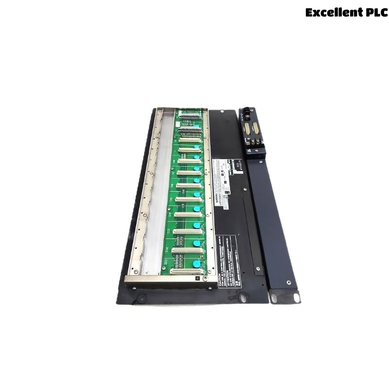
AFV10S Overview
The AFV10S is a non-redundant Field Control Unit designed for rack-mounted Field Control Stations. It performs control calculations, logic execution, alarm processing, and communication with FIO node units through Vnet/IP. The controller supports the LFS1500 Control Function package and can be expanded using the LFS1550 Node Expansion Package when additional node capacity is required.
Technical Features
- Single-controller architecture
- 19-inch rack-mounted design
- 32 MB battery-backed main memory
- Dual-redundant Vnet/IP communication
- Single or dual power supply configuration
- Automatic battery-backed memory retention
- Support for LFS1500 control functions
- Expandable using LFS1550 Node Expansion Package
Typical Industrial Applications
- Oil and gas production
- Petrochemical plants
- Chemical manufacturing
- Power generation
- Water treatment facilities
- General process automation
Installation Planning
- Review engineering documentation.
- Verify rack installation location.
- Confirm power supply requirements.
- Plan Vnet/IP network topology.
- Prepare controller configuration files.
Hardware Inspection
- Verify controller model and suffix codes.
- Inspect processor module.
- Inspect communication ports.
- Verify accessories.
- Inspect equipment for shipping damage.
Installation Environment
- Maintain adequate cabinet ventilation.
- Avoid excessive humidity.
- Protect equipment from vibration.
- Prevent conductive dust accumulation.
- Maintain specified operating temperature.
Rack Mounting Procedure
- Disconnect cabinet power.
- Install the controller into the designated rack position.
- Secure all mounting screws.
- Connect power supply cables.
- Connect communication cables.
- Verify connector engagement before energizing.
Power Supply Connections
- Connect the specified AC or DC power source.
- Verify input voltage.
- Inspect protective devices.
- Confirm wiring integrity.
- Verify power indicators after startup.
Vnet/IP and FIO Connections
- Connect redundant Vnet/IP Ethernet cables.
- Verify network switch configuration.
- Connect FIO node units.
- Confirm controller network parameters.
- Label all communication cables.
Grounding Requirements
- Connect protective earth.
- Verify rack grounding.
- Maintain low grounding resistance.
- Avoid ground loops.
- Inspect grounding continuity.
Commissioning Procedure
VERIFY INSTALLATION
CONNECT POWER
VERIFY GROUNDING
CONNECT VNET/IP
CONNECT FIO NETWORK
POWER UP CONTROLLER
DOWNLOAD APPLICATION
VERIFY COMMUNICATION
START PROCESS OPERATION
Functional Testing
- Verify controller startup.
- Confirm Vnet/IP communication.
- Verify FIO node communication.
- Validate application execution.
- Review controller diagnostics.
Preventive Maintenance
- Inspect communication wiring regularly.
- Review controller diagnostics.
- Replace backup battery according to maintenance schedules.
- Maintain configuration backups.
- Inspect cabinet cooling equipment.
Practical Installation Case
During commissioning of a wastewater treatment control system, engineers found that several FIO node units could not establish communication with the AFV10S controller.
Inspection revealed that one Vnet/IP Ethernet cable had been connected to an incorrect managed switch port during installation.
After correcting the network connection:
- All FIO node units established communication.
- Controller diagnostics returned to normal.
- The application downloaded successfully.
- The control system entered stable production service.
Frequently Asked Questions
Does the AFV10S support processor redundancy?
No. The AFV10S is a single-controller Field Control Unit. Applications requiring processor redundancy should use the AFV10D Duplexed Field Control Unit.
How much memory does the AFV10S provide?
The controller provides 32 MB of battery-backed main memory with data retention for up to approximately 72 hours after power loss.
Can the AFV10S be expanded?
Yes. The controller supports expansion using the LFS1550 Node Expansion Package to increase the number of connectable FIO node units and application capacity.
Summary
Proper installation of the Yokogawa AFV10S Field Control Unit requires secure rack mounting, reliable power connections, correct Vnet/IP and FIO network wiring, effective grounding, and comprehensive commissioning. Following these procedures ensures dependable controller performance, stable field communications, and long-term process automation reliability.