

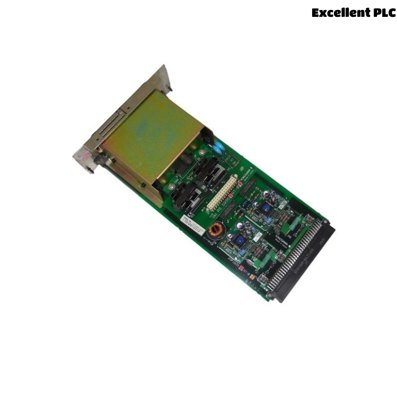
The Yokogawa AIP502 V-Net Coupler Module is a critical communication interface in Yokogawa CENTUM CS and CENTUM VP Distributed Control Systems (DCS). It connects Field Control Units (FCUs) to the V-Net real-time control network, enabling deterministic communication between controllers, operator stations, engineering stations, and higher-level system components. Failures in the AIP502 can lead to loss of controller visibility, breakdown of redundancy, or complete interruption of process data exchange. A structured troubleshooting approach is required to quickly restore network communication and ensure system stability.
Contents
- 1. Understanding V-Net Communication Faults
- 2. Common Failure Symptoms
- 3. Typical Causes of Faults
- 4. Initial Hardware Inspection
- 5. Communication Switch Verification
- 6. V-Net Cable Diagnostics
- 7. Network Status Analysis
- 8. Diagnostic Log Review
- 9. Troubleshooting Workflow
- 10. Corrective Actions
- 11. Recovery Verification
- 12. Preventive Maintenance
- 13. Real Industrial Case
- 14. Frequently Asked Questions
Understanding V-Net Communication Faults
The AIP502 ensures communication between FCUs and the V-Net backbone. Faults often manifest as controller isolation, missing nodes, intermittent communication, or redundancy failure. Most issues are caused by configuration errors, cable faults, or incorrect switch settings rather than internal hardware failure.
Common Failure Symptoms
- FCU not visible on V-Net network
- Loss of communication with operator stations
- Redundant path not active
- Intermittent data updates
- V-Net communication alarms in system diagnostics
- Engineering station cannot access controller data
- Network status LEDs show abnormal state
Typical Causes of Faults
- Switch left in DSBL mode after maintenance
- Loose or damaged V-Net cables
- Incorrect station addressing or configuration mismatch
- Faulty connectors or couplers
- Power instability in FCU or utility unit
- Incorrect redundancy configuration
- Electrical noise or grounding issues
- Internal AIP502 hardware failure (rare)
Initial Hardware Inspection
- Confirm AIP502 is fully seated in backplane
- Inspect connectors for damage or contamination
- Check FCU power stability
- Verify LED indicators on module
- Inspect cable routing and strain relief
Communication Switch Verification
- Ensure switch is set to ENBL for operation
- Confirm it was not left in DSBL after maintenance
- Toggle switch only under safe maintenance conditions
- Verify network recovery after switch correction
V-Net Cable Diagnostics
- Check cable continuity and integrity
- Inspect connector locking and alignment
- Replace damaged or aged cables
- Verify shielding and grounding quality
- Separate communication cables from power lines
Network Status Analysis
- Verify FCU presence in V-Net topology
- Check redundancy status indicators
- Confirm network domain consistency
- Review controller synchronization state
- Analyze communication delay patterns
Diagnostic Log Review
| Observed Condition | Possible Cause |
|---|---|
| FCU not detected | DSBL switch position or cable disconnection |
| Intermittent communication | Loose connector or cable degradation |
| Redundancy failure | Configuration mismatch or secondary path fault |
| Communication alarms | Network interruption or synchronization issue |
| Slow data updates | Network congestion or signal degradation |
Troubleshooting Workflow
CHECK MODULE SEATING
VERIFY SWITCH (ENBL/DSBL)
INSPECT V-NET CABLES
CHECK POWER STABILITY
REVIEW CONFIGURATION
ANALYZE SYSTEM LOGS
TEST COMMUNICATION PATHS
ISOLATE FAULT CAUSE
RESTORE NETWORK OPERATION
MONITOR STABILITY
Corrective Actions
- Set switch to ENBL if incorrectly configured
- Reconnect or replace V-Net cables
- Repair or clean connectors
- Correct station configuration mismatches
- Restore FCU power stability
- Reinitialize network communication
- Replace AIP502 only after confirming hardware failure
Recovery Verification
- Confirm FCU appears on V-Net topology
- Verify operator station connectivity
- Test real-time process data updates
- Check redundancy path activation
- Ensure absence of communication alarms
Preventive Maintenance
- Inspect connectors regularly
- Verify switch position after maintenance
- Clean and tighten connectors periodically
- Test redundancy paths during shutdowns
- Monitor communication error trends
Real Industrial Case
In a petrochemical plant, an FCU lost visibility on the V-Net network after a scheduled shutdown.
Investigation showed the AIP502 switch was left in DSBL mode after maintenance completion.
After switching to ENBL:
- FCU reappeared immediately on V-Net
- Operator stations restored communication
- Redundant path became active
- No further alarms were observed
Frequently Asked Questions
Why does the FCU disappear from V-Net?
Most commonly due to DSBL switch position, cable disconnection, or configuration mismatch.
Can cable issues cause intermittent faults?
Yes. Loose or damaged cables are a frequent cause of unstable communication.
When should the AIP502 be replaced?
Only after confirming correct configuration, stable power, intact cabling, and persistent communication failure indicating hardware fault.
Summary
Effective troubleshooting of the Yokogawa AIP502 V-Net Coupler Module requires systematic checks of switch position, cable integrity, power stability, configuration settings, and diagnostic logs. A structured approach ensures rapid recovery of communication, restoration of redundancy, and stable DCS operation.