 Excellent PLC


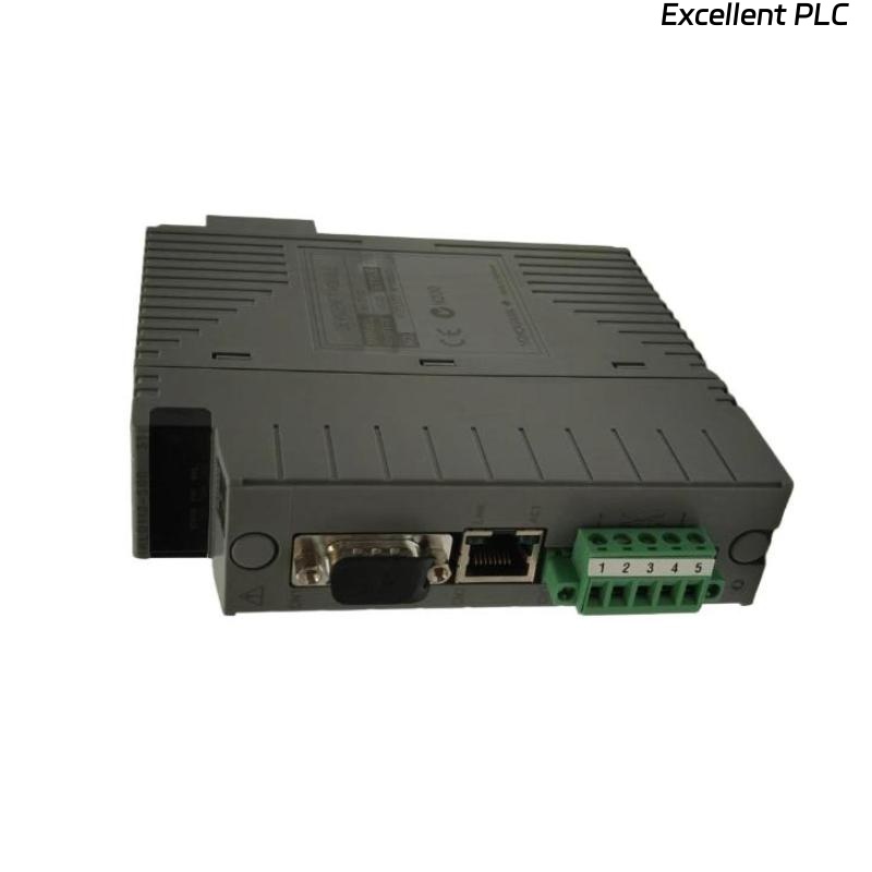
The Yokogawa ALD112-S00 S1 CPU Processor Module is the primary processing unit of a Yokogawa CENTUM VP Distributed Control System (DCS). It executes real-time control programs, manages communication with local and remote I/O modules, exchanges data over the Vnet/IP control network, and supervises overall controller operation. Because it serves as the core of the Field Control Unit (FCU), any hardware fault, configuration error, communication failure, or power-related issue may affect process control and system availability. This guide provides a systematic troubleshooting procedure for diagnosing controller startup failures, processor faults, communication errors, and abnormal operating conditions.
Contents
- 1. Understanding CPU Module Faults
- 2. Common Failure Symptoms
- 3. Typical Causes of CPU Problems
- 4. Initial Hardware Inspection
- 5. LED and Diagnostic Verification
- 6. Communication Verification
- 7. Recommended Troubleshooting Workflow
- 8. Corrective Actions
- 9. Functional Recovery Verification
- 10. Preventive Maintenance
- 11. Industrial Maintenance Case
- 12. Frequently Asked Questions
Understanding CPU Module Faults
The ALD112-S00 S1 coordinates all controller functions, including program execution, memory management, communication processing, I/O data exchange, and controller diagnostics. A failure of the CPU module may interrupt process control, generate controller alarms, prevent system startup, or disrupt communication with remote equipment. Most failures originate from power supply abnormalities, incorrect configuration, firmware incompatibility, communication network faults, module seating problems, or hardware failure.
Common Failure Symptoms
- Controller fails to start.
- CPU fault LED remains illuminated.
- Controller reset or watchdog alarms.
- Loss of communication with I/O modules.
- Controller unavailable from engineering station.
- Redundancy synchronization failure.
- Repeated controller restart.
- Abnormal diagnostic alarms.
Typical Causes of CPU Problems
- Power supply instability.
- Improper module installation.
- Damaged controller backplane connector.
- Corrupted controller database.
- Firmware incompatibility.
- Communication network failure.
- Hardware failure of the CPU module.
- Excessive cabinet temperature.
Initial Hardware Inspection
- Verify module seating within the controller chassis.
- Inspect connector pins for damage.
- Check controller power supply status.
- Inspect cabinet ventilation.
- Verify that all communication modules are correctly installed.
LED and Diagnostic Verification
- Observe CPU RUN indicator.
- Check ALARM or ERR indicators.
- Review controller diagnostic logs.
- Verify watchdog status.
- Confirm firmware and configuration compatibility.
Communication Verification
- Verify communication with local I/O modules.
- Check Vnet/IP communication status.
- Verify redundancy synchronization where applicable.
- Confirm engineering workstation connectivity.
- Inspect communication module diagnostics.
Recommended Troubleshooting Workflow
CHECK POWER SUPPLY
VERIFY CPU INSTALLATION
INSPECT LED STATUS
REVIEW DIAGNOSTIC LOGS
VERIFY NETWORK COMMUNICATION
CHECK I/O STATUS
VERIFY DATABASE CONFIGURATION
RESTART CONTROLLER
CONFIRM NORMAL OPERATION
Corrective Actions
- Reseat the CPU module securely.
- Restore stable controller power.
- Reload the verified controller database.
- Update firmware if compatibility issues exist.
- Repair communication network faults.
- Improve cabinet cooling if overheating is detected.
- Replace the CPU module if hardware failure is confirmed.
Functional Recovery Verification
- Confirm CPU RUN status is normal.
- Verify controller diagnostics report no active faults.
- Check communication with all I/O modules.
- Verify execution of all control strategies.
- Monitor controller stability during continuous operation.
Preventive Maintenance
- Inspect controller status indicators regularly.
- Monitor cabinet temperature and ventilation.
- Back up the controller database before maintenance.
- Verify firmware compatibility before upgrades.
- Inspect power supply health periodically.
- Review diagnostic logs during scheduled maintenance.
Industrial Maintenance Case
During scheduled maintenance at a petrochemical facility, a Field Control Unit failed to complete its startup sequence after a planned shutdown.
Diagnostic logs indicated a processor initialization error. Engineers determined that the controller database had become corrupted during a previous configuration update.
After loading a verified backup database and restarting the controller:
- The CPU entered normal RUN mode.
- Communication with all remote I/O modules was restored.
- Controller redundancy synchronized successfully.
- The process unit resumed stable automatic operation without further alarms.
Frequently Asked Questions
Why does the CPU module fail to start?
Common causes include unstable power, incorrect module installation, corrupted configuration data, firmware incompatibility, hardware failure, or communication network problems.
What should be checked before replacing the CPU module?
Verify the power supply, controller backplane connections, firmware version, engineering database, communication network, and diagnostic logs before concluding that the CPU hardware has failed.
Can the ALD112-S00 S1 operate in a redundant controller system?
Yes. The module is designed for CENTUM VP architectures that support controller redundancy. Both processors should be synchronized correctly, and redundancy status should be verified after maintenance or module replacement.
Summary
Effective troubleshooting of the Yokogawa ALD112-S00 S1 CPU Processor Module requires systematic verification of power supplies, hardware installation, controller diagnostics, communication networks, firmware compatibility, and engineering configuration. Proper preventive maintenance, verified configuration backups, and timely replacement of confirmed faulty hardware help ensure maximum controller availability and long-term reliability in Yokogawa CENTUM VP Distributed Control Systems.