 Excellent PLC


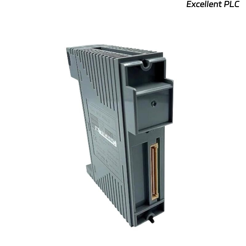
The Yokogawa AST143 TC/mV Input Module is a 16-channel isolated analog input module used in Yokogawa CENTUM VP and CENTUM CS 3000 Distributed Control Systems (DCS). The module accepts thermocouple (TC) and millivolt (mV) input signals, providing high-accuracy temperature and low-level voltage measurements for industrial process applications. Each channel can be configured independently for thermocouple or millivolt operation. The AST143 incorporates automatic cold junction compensation (CJC), channel isolation, and self-diagnostic functions. Failures affecting the module, sensors, wiring, or installation environment may result in inaccurate temperature readings, unstable measurements, or complete signal loss.
Contents
- 1. Understanding TC/mV Input Faults
- 2. Common Failure Symptoms
- 3. Typical Causes
- 4. Initial Hardware Inspection
- 5. Thermocouple and mV Signal Verification
- 6. Field Wiring Inspection
- 7. Diagnostic Analysis
- 8. Recommended Troubleshooting Workflow
- 9. Corrective Actions
- 10. Functional Recovery Verification
- 11. Preventive Maintenance
- 12. Industrial Maintenance Case
- 13. Frequently Asked Questions
Understanding TC/mV Input Faults
The AST143 continuously converts thermocouple and millivolt signals into digital process values for the DCS. Measurement errors may result from open thermocouple circuits, reversed polarity, incorrect thermocouple type selection, damaged extension cables, failed cold junction compensation, electrical noise, improper grounding, configuration errors, or internal module failures. Since thermocouple signals are measured in millivolts, proper wiring practices and environmental conditions are essential for maintaining measurement accuracy.
Common Failure Symptoms
- Temperature reading remains fixed.
- Displayed temperature is excessively high or low.
- Temperature fluctuates continuously.
- Open thermocouple alarm appears.
- Measured value differs from field reference.
- Millivolt input is unstable.
- Multiple channels fail simultaneously.
- DCS reports AST143 diagnostic alarms.
Typical Causes
- Open thermocouple circuit.
- Incorrect thermocouple polarity.
- Wrong thermocouple type configured.
- Damaged thermocouple extension cable.
- Poor cold junction compensation conditions.
- Electrical interference or improper shielding.
- Loose terminal connections.
- Incorrect engineering configuration.
- Internal AST143 hardware failure.
Initial Hardware Inspection
- Verify the AST143 is correctly installed.
- Inspect module status indicators.
- Check terminal block installation.
- Inspect cabinet grounding.
- Ensure adequate ventilation around the module.
- Review DCS diagnostic messages.
Thermocouple and mV Signal Verification
- Verify the installed thermocouple type.
- Check thermocouple polarity.
- Measure sensor continuity.
- Inspect extension cable material and type.
- Measure millivolt output with a calibrated meter.
- Verify cold junction compensation conditions.
Field Wiring Inspection
- Inspect cable continuity.
- Verify terminal numbers.
- Check extension wire connections.
- Inspect cable shielding.
- Verify grounding at one end only.
- Inspect terminal tightness.
Diagnostic Analysis
| Observed Condition | Possible Diagnosis |
|---|---|
| Temperature indicates maximum value | Open thermocouple circuit |
| Temperature decreases when process heats up | Thermocouple polarity reversed |
| Temperature offset present | Wrong thermocouple type or cold junction compensation problem |
| Unstable measurement | Electrical interference, poor grounding, or damaged extension cable |
| Multiple channels unavailable | Power supply, terminal assembly, or module failure |
Recommended Troubleshooting Workflow
CHECK DCS DIAGNOSTICS
VERIFY MODULE STATUS
VERIFY THERMOCOUPLE TYPE
CHECK POLARITY
MEASURE SENSOR CONTINUITY
INSPECT EXTENSION CABLE
VERIFY CHANNEL CONFIGURATION
CONFIRM SYSTEM RECOVERY
Corrective Actions
- Replace open thermocouples.
- Correct reversed thermocouple polarity.
- Configure the correct thermocouple type.
- Replace damaged extension cables.
- Improve grounding and shielding.
- Reposition nearby heat-generating equipment if necessary.
- Tighten terminal connections.
- Correct engineering configuration.
- Replace the AST143 if hardware failure is confirmed.
Functional Recovery Verification
- Compare measurements with a calibrated temperature source.
- Verify millivolt input accuracy.
- Check alarm operation.
- Review diagnostic information.
- Verify all sixteen channels.
- Monitor long-term measurement stability.
Preventive Maintenance
- Inspect thermocouple wiring regularly.
- Verify extension cable integrity.
- Keep terminal blocks clean and dry.
- Inspect cabinet ventilation.
- Review diagnostic history.
- Perform scheduled calibration verification.
Industrial Maintenance Case
During startup of a steam reformer, operators observed that one reactor temperature displayed by the DCS decreased while the actual process temperature was rising. Investigation revealed that the Type K thermocouple extension wires had been connected with reversed polarity during maintenance.
After correcting the wiring polarity, verifying the thermocouple type configuration, and confirming proper cold junction compensation:
- The AST143 immediately displayed the correct temperature trend.
- Temperature readings matched the portable calibrator.
- DCS diagnostic alarms cleared.
- Normal reactor temperature monitoring resumed.
Frequently Asked Questions
Why does the AST143 display an extremely high temperature?
This is typically caused by an open thermocouple circuit, broken extension cable, loose terminal connection, or sensor failure.
Why does the temperature decrease when the process is heating up?
This behavior usually indicates that the thermocouple polarity has been reversed.
What should be checked before replacing the AST143?
Verify thermocouple continuity, polarity, extension cable type, cold junction compensation conditions, engineering configuration, grounding, shielding, terminal connections, and DCS diagnostics before concluding that the AST143 module has failed.
Summary
Effective troubleshooting of the Yokogawa AST143 TC/mV Input Module requires systematic inspection of thermocouple sensors, millivolt signal circuits, extension cables, cold junction compensation, grounding, channel configuration, and DCS diagnostics. Regular preventive maintenance, proper thermocouple installation, and periodic calibration ensure accurate temperature measurement and reliable long-term operation of Yokogawa CENTUM Distributed Control Systems.