

Yokogawa SNB10D-213/CN2N installation problems are typically caused by ESB Bus addressing conflicts, connector unit configuration mistakes, or power distribution issues rather than defects in the Safety Node Unit itself. As a rack-mounted Safety Node Unit for Yokogawa ProSafe-RS systems, the SNB10D-213/CN2N provides communication between field I/O modules and the Safety Control Unit (SCU) while supplying power to connected modules through the ESB Bus architecture. :contentReference[oaicite:0]{index=0}
Contents
- SNB10D-213/CN2N Safety Node Unit Overview
- SNB10D-213/CN2N Role in Safety Systems
- Installation Planning for SNB10D-213/CN2N
- Safety Node Unit Environmental Requirements
- SNB10D-213/CN2N Power Supply Preparation
- Rack Installation Requirements
- Pre-Installation Inspection
- SNB10D-213/CN2N Installation Guide
- ESB Bus Setup Procedure
- Safety I/O Allocation Strategy
- Grounding and EMC Practices
- Initial Startup Verification
- SNB10D-213/CN2N Setup Workflow
- System Configuration Validation
- Commissioning Sequence
- Redundancy Verification
- Real Commissioning Case
- FAQ
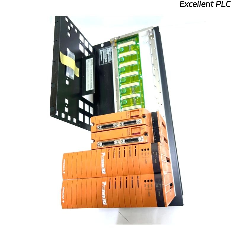
SNB10D-213/CN2N Safety Node Unit Overview
The SNB10D-213/CN2N is a rack-mountable Safety Node Unit designed for Yokogawa ProSafe-RS systems. The unit communicates with the Safety Control Unit through the ESB Bus and distributes power to connected safety I/O modules. It supports dual-redundant power architectures and ESB communication networks. :contentReference[oaicite:1]{index=1}
SNB10D-213/CN2N Role in Safety Systems
- Safety signal acquisition
- Distributed I/O communication
- Emergency shutdown integration
- Fire and gas system support
- Power distribution for I/O modules
Installation Planning for SNB10D-213/CN2N
Successful projects begin with engineering preparation.
- Determine node quantity
- Review ESB network topology
- Define communication paths
- Allocate safety loops
- Plan future expansion capacity
Safety Node Unit Environmental Requirements
- Temperature control
- Humidity management
- Low vibration environment
- EMC-compliant installation area
- Adequate maintenance access
SNB10D-213/CN2N Power Supply Preparation
The unit supports multiple power supply options and dual-redundant power configurations. :contentReference[oaicite:2]{index=2}
- Verify input voltage
- Confirm power redundancy
- Inspect protection devices
- Validate grounding continuity
Rack Installation Requirements
- 19-inch rack installation
- Four-point mechanical support
- Cable routing space
- Ventilation clearance
Proper rack installation improves long-term reliability. :contentReference[oaicite:3]{index=3}
Pre-Installation Inspection
- Verify model number
- Inspect ESB connectors
- Check shipping damage
- Verify connector unit integrity
- Confirm documentation availability
SNB10D-213/CN2N Installation Guide
- Isolate cabinet power.
- Prepare rack position.
- Install the Safety Node Unit.
- Secure mounting screws.
- Inspect alignment.
- Verify mechanical stability.
ESB Bus Setup Procedure
- Verify connector orientation
- Inspect bus termination
- Confirm communication path
- Validate redundancy connections
- Review network architecture
Incorrect ESB Bus connections are among the most common commissioning issues.
Safety I/O Allocation Strategy
- Digital input grouping
- Digital output allocation
- Analog signal mapping
- Safety loop segregation
- Shutdown function assignment
Grounding and EMC Practices
- Protective earth verification
- Shield termination inspection
- Cabinet bonding validation
- Ground loop prevention
Initial Startup Verification
- Power LED inspection
- Communication status verification
- Alarm review
- I/O module recognition check
SNB10D-213/CN2N Setup Workflow
POWER ON SYSTEM
VERIFY NODE STATUS
CHECK ESB COMMUNICATION
VALIDATE I/O ASSIGNMENTS
SAVE CONFIGURATION
RECORD BASELINE VALUES
System Configuration Validation
- Node address verification
- I/O mapping validation
- Safety application review
- Communication route verification
- Redundancy confirmation
Commissioning Sequence
- Verify hardware installation.
- Validate communication.
- Test field signals.
- Verify shutdown logic.
- Execute integrated testing.
Redundancy Verification
- Power failover testing
- Communication failover validation
- Node recovery testing
- Alarm response verification
Real Commissioning Case
During commissioning of a petrochemical SIS upgrade project, operators reported that multiple safety inputs connected through an SNB10D-213/CN2N were unavailable.
Measured values included:
- Supply voltage: 118.7 VAC
- ESB latency: 14 ms
- Communication diagnostics: healthy
- Missing signals: 12 channels
Initial suspicion focused on the Safety Node Unit hardware. However, detailed investigation showed duplicated channel assignments inside the System Configuration database.
After correcting the configuration:
- All channels became visible
- Safety loops passed testing
- No communication alarms remained
- Commissioning completed successfully
We observed that database configuration errors generated symptoms nearly identical to hardware faults.
SNB10D-213/CN2N Installation Guide FAQ
What is the main function of the SNB10D-213/CN2N?
It serves as a Safety Node Unit that transfers field I/O information to the Safety Control Unit through the ESB Bus while supplying power to connected modules. :contentReference[oaicite:4]{index=4}
Does the unit support redundant communication?
Yes. The architecture supports dual-redundant ESB Bus communication for high-availability safety applications. :contentReference[oaicite:5]{index=5}
Why is System Configuration validation important?
Addressing and I/O mapping errors are among the most common causes of startup and commissioning failures.
Summary: A successful Yokogawa SNB10D-213/CN2N Installation Guide requires proper Setup, accurate System Configuration, disciplined Commissioning procedures, and complete validation of ESB communication and safety functions.