

Yokogawa SNT411-5F installation challenges are most often related to optical fiber design mistakes, ESB network architecture issues, or incomplete System Configuration rather than failures of the Optical ESB Bus Repeater Master Module itself. Because the SNT411-5F serves as the communication hub between optical ESB segments and distributed safety nodes, proper installation and commissioning directly influence the reliability of the entire control network.
Contents
- SNT411-5F Optical ESB Bus Repeater Master Module Overview
- Role of SNT411-5F in ESB Communication Networks
- ESB Network Architecture Design
- Fiber Infrastructure Planning
- Site Requirements Before Installation
- Hardware Inspection Checklist
- SNT411-5F Module Installation Guide
- Optical Fiber Connection Procedure
- Power Supply and Grounding Verification
- SNT411-5F Setup Procedure
- System Configuration Validation
- Communication Verification
- Commissioning Strategy
- Redundancy Testing
- Network Performance Assessment
- Maintenance Recommendations
- Real Commissioning Case
- FAQ
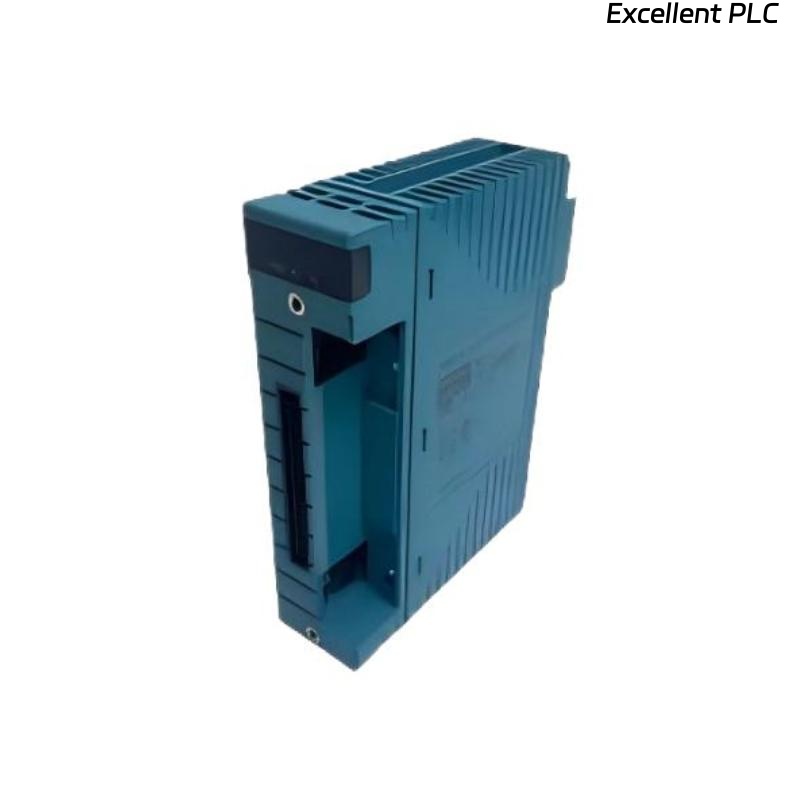
SNT411-5F Optical ESB Bus Repeater Master Module Overview
The Yokogawa SNT411-5F Optical ESB Bus Repeater Master Module functions as the master-side optical communication interface within Yokogawa ESB Bus networks. It manages communication with SNT511-series repeater slave modules and enables long-distance optical transmission between distributed safety and control system components.
The module is commonly deployed in large-scale process plants where reliable communication over several kilometers is required.
Role of SNT411-5F in ESB Communication Networks
- Master communication management
- Optical ESB bus conversion
- Long-distance communication support
- Network expansion capability
- Distributed node integration
- Communication redundancy support
As the master communication point, the SNT411-5F plays a critical role in maintaining communication continuity.
ESB Network Architecture Design
Before installation, engineers should evaluate:
- Communication topology
- Node quantity
- Optical repeater allocation
- Safety node locations
- Redundancy requirements
- Future expansion capacity
Network architecture planning significantly reduces future Troubleshooting activities.
Fiber Infrastructure Planning
- Route selection
- Fiber type verification
- Patch panel allocation
- Splice location planning
- Attenuation budgeting
Many communication faults can be prevented through proper fiber design.
Site Requirements Before Installation
- Stable ambient temperature
- Proper cabinet ventilation
- Adequate rack space
- Low electromagnetic interference
- Reliable grounding infrastructure
Hardware Inspection Checklist
- Inspect module housing
- Verify optical connectors
- Confirm part number
- Check shipping condition
- Inspect backplane contacts
Pre-installation inspection helps avoid unnecessary startup delays.
SNT411-5F Module Installation Guide
- Shut down cabinet power.
- Verify rack readiness.
- Insert the SNT411-5F module.
- Secure mounting mechanisms.
- Inspect connector engagement.
- Document installation records.
Mechanical installation should be completed before any optical connection work begins.
Optical Fiber Connection Procedure
Fiber communication quality directly affects ESB network stability.
- Verify transmit paths
- Verify receive paths
- Inspect connector cleanliness
- Measure optical attenuation
- Confirm route identification
Field experience shows that contaminated connectors are responsible for a large percentage of startup communication alarms.
Power Supply and Grounding Verification
- Verify supply voltage
- Inspect grounding conductors
- Check cabinet bonding
- Validate shield connections
Grounding quality directly impacts communication reliability.
SNT411-5F Setup Procedure
POWER ON SYSTEM
CHECK MODULE STATUS
VERIFY OPTICAL LINK
CHECK NODE RECOGNITION
VALIDATE COMMUNICATION
SAVE BASELINE PARAMETERS
These baseline values are useful during future Fault Diagnosis activities.
System Configuration Validation
- Node address verification
- Communication route review
- Repeater assignment checks
- Redundancy validation
- Safety network confirmation
Configuration mistakes often generate symptoms identical to communication hardware failures.
Communication Verification
- Node visibility testing
- Response time analysis
- Error counter review
- Link integrity verification
- Alarm history inspection
SNT411-5F Commissioning Strategy
Rather than energizing the entire network immediately, successful commissioning typically follows a staged approach.
- Verify hardware installation.
- Test individual communication links.
- Validate network segments.
- Confirm node communications.
- Perform integrated testing.
This strategy minimizes startup risk.
Redundancy Testing
- Fiber disconnection simulation
- Node failover testing
- Power recovery verification
- Communication restoration assessment
Redundancy validation is essential in safety-related applications.
Network Performance Assessment
- Communication latency
- Error rate monitoring
- Retry analysis
- Node response time
- Long-term stability testing
Maintenance Recommendations
- Quarterly fiber inspection
- Annual attenuation testing
- Connector cleaning procedures
- Configuration backup reviews
- Network trend monitoring
Real SNT411-5F Commissioning Case
During startup of a fertilizer production facility, operators reported unstable communication between the central safety system and remote process units.
Initial measurements showed:
- Communication latency: 240 ms
- Fiber attenuation: 8.2 dB
- Multiple retry events
- No module hardware alarms
The engineering team initially suspected a defective Optical ESB Bus Repeater Master Module.
However, detailed investigation found that two fiber connectors had not been properly cleaned during installation.
After cleaning and re-testing:
- Fiber attenuation reduced to 2.7 dB
- Latency decreased to 16 ms
- Error counters stabilized
- Communication alarms disappeared
We observed that installation quality had a greater impact on network stability than replacing communication hardware.
SNT411-5F Installation Guide FAQ
What is the primary role of the SNT411-5F?
The module acts as the master communication interface for optical ESB bus networks and manages communication with repeater slave modules.
Why is fiber attenuation important during commissioning?
Excessive attenuation can cause communication retries, latency increases, and intermittent communication failures.
What should be verified before startup?
Fiber quality, Setup parameters, communication status, and System Configuration should all be validated before commissioning.
Summary: A successful Yokogawa SNT411-5F Installation Guide requires proper fiber infrastructure planning, accurate Setup procedures, complete System Configuration validation, and structured Commissioning testing to ensure long-term communication reliability.