

Yokogawa SNT501-E3 installation issues are most commonly caused by incorrect optical fiber routing, ESB Bus topology errors, or incomplete System Configuration rather than faults within the Optical ESB Bus Repeater Module itself. Successful commissioning depends on verifying optical signal quality before network startup and ensuring communication paths are properly designed. The SNT501-E3 converts ESB Bus communication into optical transmission, allowing communication distances of up to 5 km and up to 10 km in supported Vnet/IP systems. :contentReference[oaicite:0]{index=0}
Contents
- SNT501-E3 Optical ESB Bus Repeater Module Overview
- Role of SNT501-E3 in ESB Networks
- Fiber Network Planning Strategy
- Hardware Inspection Before Installation
- Environmental Requirements
- SNT501-E3 Module Installation Guide
- Optical Fiber Connection Guide
- ESB Bus Interface Connection
- Grounding and EMC Protection
- SNT501-E3 Setup Procedure
- System Configuration Verification
- Optical Signal Validation
- Commissioning Workflow
- Network Validation Tests
- Real Commissioning Experience
- FAQ
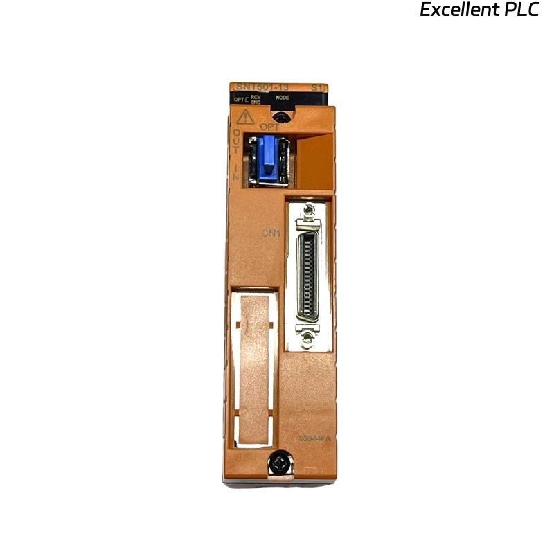
SNT501-E3 Optical ESB Bus Repeater Module Overview
The Yokogawa SNT501-E3 Optical ESB Bus Repeater Module extends ESB Bus communication through optical fiber technology. The module connects to an Optical ESB Bus Repeater Master Module (SNT401) or N-ESB Bus Module and interfaces with the SSB401 ESB Bus Interface Module installed on a Safety Node Unit. :contentReference[oaicite:1]{index=1}
Role of SNT501-E3 in ESB Networks
- Extends communication distance
- Supports remote safety node installation
- Improves communication reliability
- Provides optical signal transport
- Supports star and chain topology networks
The module is frequently used in large refinery, petrochemical, LNG, and power generation facilities where long-distance communication is required. :contentReference[oaicite:2]{index=2}
Fiber Network Planning Strategy
Before installation, engineers should review:
- Fiber routing diagrams
- Node allocation plans
- Redundant communication paths
- Transmission distance calculations
- Attenuation budgets
Incorrect topology planning often creates communication instability during commissioning.
Hardware Inspection Before Installation
- Inspect module housing
- Verify connector integrity
- Check optical interfaces
- Review part number and revision
- Confirm compatibility with network design
Environmental Requirements for SNT501-E3 Installation
The module supports ISA G3 environments and operating temperatures from -20°C to 70°C for maintenance conditions. :contentReference[oaicite:3]{index=3}
- Clean cabinet environment
- Stable ambient temperature
- Proper ventilation
- Controlled humidity
- Protection from vibration
SNT501-E3 Module Installation Guide
- Isolate cabinet power.
- Inspect rack connectors.
- Install the module securely.
- Verify locking mechanisms.
- Inspect optical ports.
- Record installation information.
Physical installation should always be completed before optical fiber connection.
Optical Fiber Connection Guide
The SNT501-E3 supports single-mode optical fiber communication. Fiber quality directly impacts communication reliability. :contentReference[oaicite:4]{index=4}
- Verify transmit and receive paths
- Clean optical connectors
- Inspect connector end faces
- Measure attenuation values
- Confirm cable labels
ESB Bus Interface Connection
The module communicates with the SSB401 ESB Bus Interface Module installed in the Safety Node Unit through ESB Bus cabling. :contentReference[oaicite:5]{index=5}
Grounding and EMC Protection
- Verify protective earth continuity
- Inspect cabinet bonding
- Check shield termination
- Review cable separation requirements
Good grounding practices help eliminate intermittent communication faults.
SNT501-E3 Setup Procedure
VERIFY POWER STATUS
CHECK OPTICAL LINK
VERIFY NODE DETECTION
CHECK COMMUNICATION STATUS
RECORD BASELINE VALUES
System Configuration Verification
- Node address validation
- Repeater assignment review
- Communication route verification
- Redundancy parameter checks
- Network segment allocation
Optical Signal Validation
Before startup, engineers should measure:
- Fiber attenuation
- Signal quality
- Network latency
- Error counters
- Communication retries
Optical attenuation outside design limits frequently causes commissioning delays.
SNT501-E3 Commissioning Workflow
- Verify hardware installation.
- Check optical communication.
- Confirm node accessibility.
- Perform communication load testing.
- Validate failover behavior.
- Record final performance values.
Network Validation Tests
- Normal operation verification
- Fiber disconnection testing
- Redundancy validation
- Communication recovery testing
- Alarm simulation
Real SNT501-E3 Commissioning Experience
During commissioning of a petrochemical expansion project, engineers experienced intermittent communication alarms affecting two remote safety nodes.
Measured values included:
- Fiber attenuation: 7.9 dB
- Communication latency: 185 ms
- Error retries: continuously increasing
- Power status: normal
Initial assumptions focused on replacing the Optical ESB Bus Repeater Module.
However, further investigation revealed excessive bending radius violations in a newly installed fiber tray.
After rerouting the fiber cable:
- Attenuation decreased to 2.3 dB
- Latency dropped below 20 ms
- Error counters stabilized
- Communication alarms disappeared
We observed that installation quality had a greater influence on communication stability than hardware replacement.
SNT501-E3 Installation Guide FAQ
What is the primary function of the SNT501-E3?
The module converts ESB Bus communication into optical transmission to extend communication distance within Yokogawa safety networks.
What network topologies are supported?
Both star and chain connection methods are supported. :contentReference[oaicite:6]{index=6}
What should be checked before commissioning?
Fiber attenuation, System Configuration, communication diagnostics, and node visibility should all be verified.
Summary: A successful Yokogawa SNT501-E3 Installation Guide requires proper fiber management, accurate Setup procedures, reliable System Configuration, and thorough Commissioning validation to ensure long-term network stability.