

Scenario Introduction
Imagine you’re commissioning a new HC900 / Experion PKS network, and the 10018/E/1 FSC Ethernet module is not showing up on the network. What went wrong? Often, installation mistakes—not hardware defects—are the culprit.
This guide walks you through installation steps while highlighting typical pitfalls, ensuring the module works reliably.
1️⃣ Understanding the Module
-
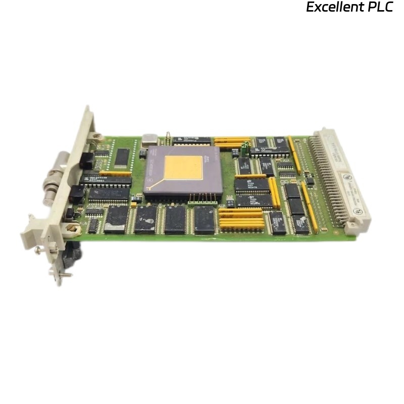
Purpose: Connects HC900 or Experion systems to Ethernet networks for SCADA communication.
-
Common Issues:
-
Module not detected
-
LEDs not showing correct status
-
Network conflicts or intermittent connectivity
-
Knowing what can go wrong helps you avoid these issues during installation.
2️⃣ Pre-Installation Checks
Common Mistakes:
-
Installing while rack power is on → can damage network interfaces.
-
Incorrect module slot selection → causes link errors.
-
Dirty or bent backplane pins → prevents proper module recognition.
Best Practice:
-
Always power down the rack completely.
-
Confirm module type 10018/E/1 FSC matches the system specification.
-
Inspect slot and backplane connector for dirt or oxidation.
3️⃣ Module Installation
Step-by-Step with Caution Notes:
-
Slot Alignment:
-
Ensure the module’s edge connector is aligned with the slot.
-
Mistake to avoid: Forcing module at an angle → bent pins.
-
-
Seating the Module:
-
Slide the module firmly until you feel it click into place.
-
Secure any retention clips.
-
Common issue: Loose seating → module powers on but COM LED fails.
-
-
Cable Connection:
-
Connect Ethernet cable to the port.
-
Check shielding and grounding to reduce EMI interference.
-
Avoid: Twisting or tension on cables, which can reduce long-term reliability.
-
4️⃣ Power On and Verification
-
Restore rack power.
-
LED Indicators:
-
PWR: Solid green → module powered
-
LINK/ACT: Blinking green → active network connection
-
FAULT: Off → normal operation
-
-
Verify network communication from the engineering workstation: IP address assignment, SCADA recognition, ping test.
Tip: If the module fails to communicate, first check IP conflicts, subnet mask, and physical cable condition before assuming module failure.
5️⃣ Troubleshooting Common Errors
| Error Scenario | Likely Cause | Solution |
|---|---|---|
| LINK LED off | Cable disconnected/damaged | Replace or reconnect cable |
| FAULT LED on | Node address conflict | Verify unique address in network |
| Module not detected | Improper seating | Re-seat module in backplane slot |
| Intermittent connection | EMI interference | Reroute cable away from power lines |
6️⃣ Best Practices for Longevity
-
Label all network cables to avoid confusion during maintenance.
-
Record installation date and firmware version.
-
Inspect cables and connectors every 6–12 months.
-
Avoid repeated hot-swapping; always power down before removing/installing modules.
Summary
Think of installation as avoiding preventable mistakes rather than fixing failures:
Preparation → Slot inspection → Module seating → Cable connection → Power on & verification → Monitor LEDs → Record installation
By understanding why modules fail and not just how to insert them, your Honeywell 10018/E/1 FSC Ethernet module will provide reliable communication in your network.