

1️⃣ Introduction
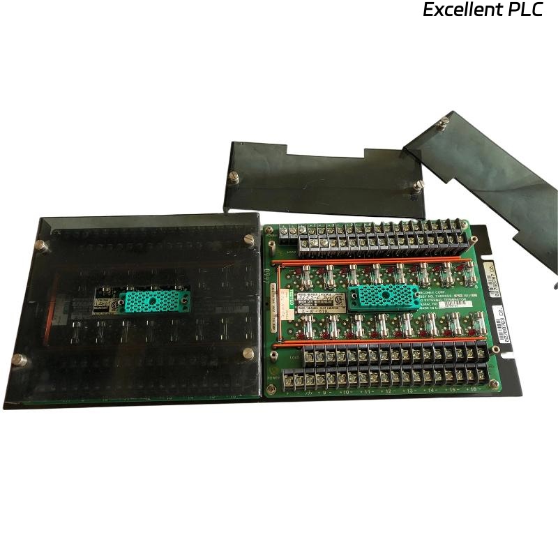
The Triconex 3000120-360 DI External Terminator is a critical component in the Tricon safety system, designed to provide signal termination and isolation for Digital Input (DI) modules.
Proper installation of this unit ensures signal integrity, system reliability, and long-term operational safety within Triple Modular Redundant (TMR) architectures.
2️⃣ Technical Overview
| Parameter | Specification |
|---|---|
| Model | Triconex 3000120-360 |
| Type | Digital Input (DI) External Terminator |
| Application | Used with DI modules to ensure correct field signal termination |
| Connection Type | Screw terminal interface |
| Typical Voltage Range | 24 VDC signal input |
| Environment | Industrial control cabinets, Tricon rack interface |
The terminator provides proper impedance matching and noise suppression between field devices and the Tricon DI module backplane, preventing signal reflection and false state detection.
3️⃣ Pre-Installation Requirements
Before installation, confirm the following prerequisites:
-
Ensure Tricon rack power is OFF before any wiring activity.
-
Verify compatibility: 3000120-360 matches the target DI module model.
-
Prepare shielded signal cables to minimize EMI interference.
-
Use anti-static protection (ESD wrist strap) when handling modules.
-
Confirm mounting location allows free airflow and cable clearance.
⚠️ Safety Note: Working with powered systems can cause unintended logic input activation or permanent module damage. Always de-energize before installation.
4️⃣ Installation Procedure
-
Position the Terminator
-
Locate the designated terminal block position adjacent to the DI module rack.
-
Ensure the labeling corresponds to the correct channel numbers.
-
-
Wire the Input Channels
-
Connect each field input wire to its respective channel terminal.
-
Maintain consistent polarity (+ / –) for 24VDC signals.
-
Tighten all terminal screws using a torque screwdriver (0.5–0.6 N·m).
-
-
Connect the Common and Shield
-
Bond all common lines to the designated ground bus.
-
Connect shielding only at the control cabinet end to prevent ground loops.
-
-
Inspect and Verify Connections
-
Perform a continuity test on each input channel.
-
Label cables for future maintenance traceability.
-
5️⃣ Post-Installation Checks
After wiring is complete and before system energization:
-
Inspect all terminal points for tightness and insulation damage.
-
Use a multimeter to verify proper voltage levels at each input.
-
Confirm no short circuits between adjacent channels.
-
Restore power and observe DI module status LEDs to verify normal operation.
Normal LED status:
-
RUN (Green): Steady ON
-
FLT (Red): OFF
-
CH LED: Reflects field signal state changes
6️⃣ Common Installation Errors and Solutions
| Issue | Likely Cause | Recommended Action |
|---|---|---|
| False ON/OFF readings | Poor shielding or loose terminal | Tighten terminals, recheck shielding |
| DI channel not responding | Incorrect wiring or open circuit | Verify continuity and channel mapping |
| Module fault after power-up | Shorted input or incorrect polarity | Inspect wiring and replace damaged cable |
| Signal fluctuation | Ground loop or EMI | Connect shield at one end only |
7️⃣ Engineering Recommendations
-
Perform annual inspection of all terminal connections.
-
Keep terminal labels consistent with PLC logic documentation.
-
Maintain a clean and dry cabinet environment (< 40°C, < 75% RH).
-
Use factory-approved ferrules and avoid bare wire insertion.
-
Always update maintenance logs after any wiring change.
✅ Conclusion
The Triconex 3000120-360 DI External Terminator plays a vital role in maintaining input signal stability and overall TMR system reliability.
Following the correct installation and wiring procedures minimizes risk of false inputs, improves diagnostic accuracy, and extends system life.
In short:
Proper termination = stable logic = safer plant operation.