

1. Overview
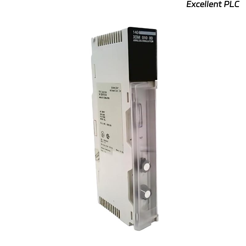
The Schneider 140XSM40010 is a Signal Isolation and Conversion Module designed for use within Modicon Quantum automation systems.
It provides galvanic isolation and signal buffering between field analog devices and I/O channels, effectively preventing ground loops and electrical noise interference.
🔍 Its correct installation is critical for ensuring measurement accuracy and communication reliability in analog signal networks.
2. Module Identification
| Specification | Description |
|---|---|
| Model | 140XSM40010 |
| Type | Analog Signal Isolator / Conditioner |
| Channels | 4 isolated analog channels |
| Input Type | Voltage or current (configurable) |
| Output Type | 4–20 mA or 0–10 VDC |
| Isolation Voltage | 1500 V RMS between channels and ground |
| Mounting | DIN-rail inside Quantum I/O enclosure |
3. Safety Precautions
Before installation, ensure:
-
Power to the Quantum rack is completely disconnected.
-
Follow ESD protection procedures — wear anti-static wrist straps.
-
Verify the module’s firmware and hardware version match system requirements.
-
Avoid installation in environments with excessive vibration, moisture, or EMI.
⚠️ Warning: Incorrect wiring or grounding may cause signal drift or permanent damage to the isolator.
4. Installation Procedure
Step 1: Prepare the Installation Area
-
Verify available space in the control cabinet.
-
Ensure proper ventilation clearance (minimum 25 mm on all sides).
-
Clean the DIN-rail surface to ensure good contact.
Step 2: Mount the Module
-
Position the 140XSM40010 module onto the DIN-rail.
-
Gently press the top first, then snap the bottom latch until it locks securely.
-
Verify mechanical stability — the module should not wobble or shift.
🧩 Tip: Use vibration-resistant mounting if installed in high-load industrial panels.
Step 3: Wiring Connections
Each channel on the 140XSM40010 provides isolated input and output terminals.
| Terminal Mark | Function | Description |
|---|---|---|
| IN+ / IN– | Analog Input | Connect field signal (e.g., transmitter, sensor) |
| OUT+ / OUT– | Analog Output | Connect to PLC analog input module |
| GND | Shield Ground | Connect cable shield; avoid double grounding |
Wiring Notes:
-
Use twisted shielded cables (AWG 22–24) for all analog signals.
-
Ground shields at one end only (preferably module end).
-
Separate analog and power cables to minimize interference.
Step 4: Power and Ground Verification
-
Ensure the 24 VDC supply meets Schneider’s recommended voltage tolerance (±10%).
-
Measure between +24V and GND before powering the module.
-
Confirm that the panel grounding resistance is <5 Ω.
Step 5: Configuration and Calibration
The 140XSM40010 supports input/output range configuration via onboard DIP switches or software (depending on variant).
| Setting | Function |
|---|---|
| SW1 | Select current/voltage input mode |
| SW2 | Select output scaling (4–20 mA / 0–10 V) |
| SW3 | Enable/disable filtering mode |
Calibration Procedure:
-
Apply a known reference input (e.g., 4 mA).
-
Measure the output — adjust trimmers if deviation >0.1%.
-
Repeat for upper range (e.g., 20 mA).
-
Save settings and verify repeatability.
⚙️ Always perform calibration after any firmware update or module replacement.
Step 6: Power-On Test
-
Reconnect rack power and observe module status LED:
-
Green ON: Normal operation
-
Flashing Amber: Configuration required
-
Red ON: Hardware fault — recheck wiring or calibration
-
-
Check PLC analog input readings — they should match reference signal within tolerance.
5. Integration with Modicon Quantum System
To link the 140XSM40010 with the Quantum I/O system:
-
Connect the module’s analog outputs to Quantum 140ACI04000 or similar analog input modules.
-
In EcoStruxure Control Expert / Unity Pro, assign channel scaling to match output range.
-
Validate I/O mapping and run diagnostic checks.
✅ Once recognized, the module transmits clean, isolated analog data for precise control operations.
6. Maintenance Recommendations
| Action | Frequency | Purpose |
|---|---|---|
| Visual inspection | Every 6 months | Check connectors, terminal oxidation |
| Calibration verification | Yearly | Maintain measurement accuracy |
| Firmware version check | Annually | Ensure compatibility with Quantum system |
| Grounding integrity test | Every shutdown | Avoid noise interference and ground loops |
7. Common Installation Mistakes
| Mistake | Result | Corrective Measure |
|---|---|---|
| Shield grounded at both ends | Ground loop noise | Ground at one end only |
| Power shared with inductive loads | Voltage ripple | Use isolated 24V supply |
| Tight cable bends | Signal distortion | Maintain bend radius > 5× cable diameter |
| Missing ventilation | Thermal drift | Ensure proper airflow |
8. Summary
The Schneider 140XSM40010 analog isolation module ensures signal integrity, system protection, and measurement accuracy in industrial environments.
By following correct installation and calibration procedures — including shielding, grounding, and verification — users can achieve long-term stable operation within Modicon Quantum systems.
“In precision automation, isolation is not just protection — it’s the foundation of accuracy.”