

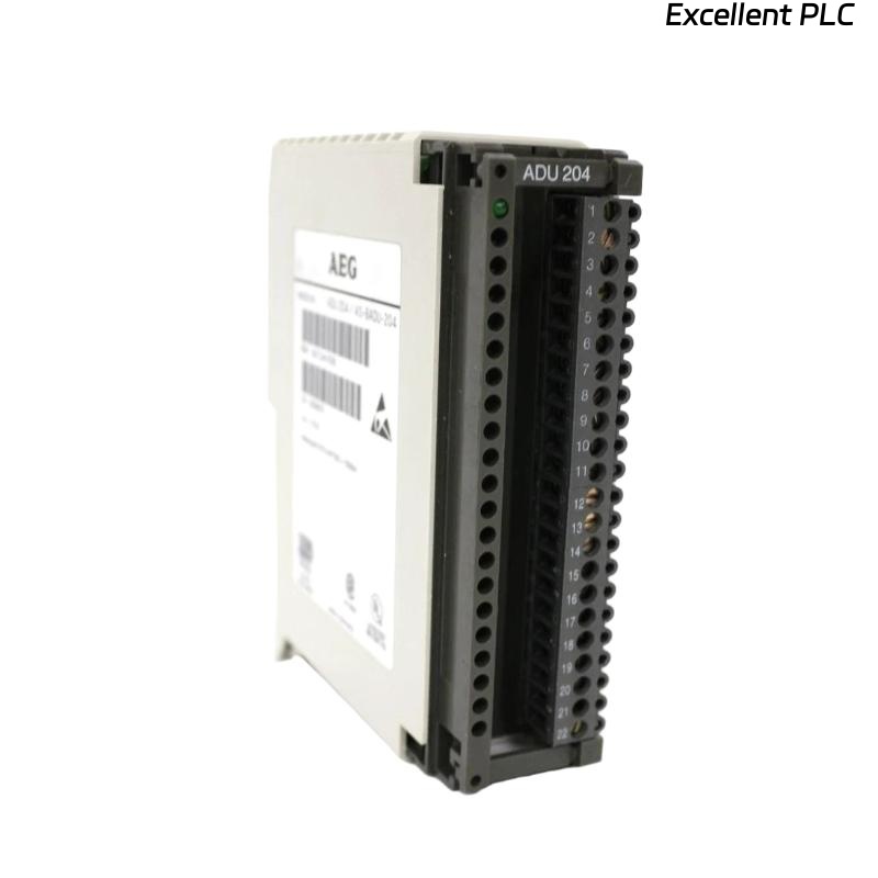
When it comes to analog signal acquisition in Schneider PLC systems, the ADU 204 (AS-BADU-204) module plays a crucial role.
It’s widely used in industrial automation, process monitoring, and distributed control systems, converting field analog signals into precise digital data for the CPU.
If you’re setting up or replacing one of these modules, this step-by-step guide will walk you through the installation, wiring, and commissioning process — with some field-proven tips to ensure stability and accuracy.
🧾 1. Understanding the Schneider ADU 204 Module
Before diving into the installation, it’s important to know what this unit does:
| Feature | Description |
|---|---|
| Model Name | Schneider ADU 204 / AS-BADU-204 |
| Function | 4-channel analog input unit |
| Input Type | 4–20 mA / 0–10 V (software-selectable) |
| Resolution | 12 or 16-bit (depending on configuration) |
| Mounting | Rack-mounted module, used with Modicon or Compact PLC series |
| Power Supply | 24 VDC |
| Isolation | Channel-to-channel and system isolation for noise immunity |
💡 The ADU 204 ensures reliable analog signal acquisition, even in high-EMI industrial environments.
⚙️ 2. Tools and Preparations
Before starting, make sure you have:
-
Anti-static wrist strap (for ESD protection)
-
Flat-head screwdriver (2.5 mm)
-
Shielded twisted-pair cables for analog signal wiring
-
Multimeter (for signal verification)
-
Schneider installation manual or wiring diagram (for reference)
Safety First: Always power down the PLC rack before inserting or removing any I/O module.
🧩 3. Installation Steps
Step 1: Prepare the Mounting Slot
Locate an empty I/O slot in your rack that supports the ADU 204 form factor.
Check for sufficient clearance — at least 30 mm of free space above and below for airflow.
Step 2: Insert the Module
-
Hold the module by its edges — avoid touching the connector pins.
-
Align it with the guide rails of the rack.
-
Slide gently until it clicks into position.
-
Tighten the retaining screws on both sides (if applicable).
✅ Tip: The module should seat firmly; loose installation may cause intermittent communication errors.
🔌 4. Wiring the Analog Inputs
Each of the four channels can be configured for current or voltage input.
Here’s a basic connection layout:
| Terminal | Function | Typical Wiring |
|---|---|---|
| CH1+ / CH1– | Analog Input 1 | 4–20 mA or 0–10 V signal |
| CH2+ / CH2– | Analog Input 2 | 4–20 mA or 0–10 V signal |
| CH3+ / CH3– | Analog Input 3 | 4–20 mA or 0–10 V signal |
| CH4+ / CH4– | Analog Input 4 | 4–20 mA or 0–10 V signal |
| COM | Common reference | Connect to analog ground (AGND) |
| SHIELD | Cable shielding | Ground at one end only |
Wiring Best Practices:
-
Keep analog cables separate from digital or power lines.
-
Use shielded twisted pair to minimize noise.
-
Ensure all cable shields terminate on the same grounding point.
⚡ If the plant environment has high-frequency interference, consider adding ferrite cores to the analog lines.
🧠 5. Configuring the Module
After installation and wiring, it’s time to configure the module using Schneider’s engineering software — Concept, ProWORX, or EcoStruxure Control Expert, depending on your PLC system.
Configuration Steps:
-
Open your PLC project.
-
Locate the slot containing the ADU 204 module.
-
Select the channel mode:
-
Voltage Mode: for 0–10 V sensors
-
Current Mode: for 4–20 mA transmitters
-
-
Set the scaling (e.g., 0–10 V = 0–100%) and signal range.
-
Download configuration to the PLC and verify status.
✅ Tip: Always perform a live test by injecting a known analog value (e.g., 12 mA) and checking the reading in your PLC variable table.
🔍 6. Troubleshooting Common Installation Issues
| Symptom | Possible Cause | Solution |
|---|---|---|
| Module not detected | Loose rack connection | Reseat module, clean contacts |
| No input reading | Wrong wiring polarity | Swap + and – terminals |
| Unstable values | Grounding or EMI noise | Improve shielding and grounding |
| All channels show same value | Configuration mismatch | Recheck channel mapping and mode |
🧩 7. Maintenance and Best Practices
| Task | Frequency | Purpose |
|---|---|---|
| Visual inspection | Every 6 months | Check terminals and cables |
| Calibration verification | Annually | Maintain signal accuracy |
| Firmware updates | As released | Fix bugs, improve performance |
| Rack cleaning | Annually | Prevent dust accumulation and overheating |
🧰 A clean, well-grounded cabinet is the best insurance for analog signal accuracy.
✅ 8. Final Verification
After setup:
-
Power on the PLC rack.
-
Check the module’s LED indicators:
-
RUN (Green): Normal operation
-
ERR (Red): Configuration or hardware fault
-
-
Open your engineering software and verify the input values in real time.
Once readings are stable and match the reference, the installation is complete.
🏁 Final Thoughts
Installing the Schneider ADU 204 / AS-BADU-204 module isn’t difficult — but attention to grounding, cable routing, and configuration makes all the difference.
Many analog signal issues in industrial systems come not from faulty modules, but from poor installation practices.
“Precision in wiring is precision in data — that’s the golden rule for analog systems.”