

💡 Overview
If you’re setting up or replacing a Schneider 170CPS11100 M1 module in your Modicon Momentum system, this guide walks you through the process safely and efficiently.
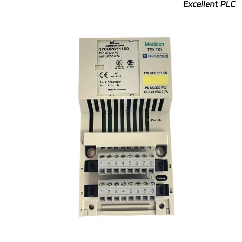
The 170CPS11100 M1 is a power supply module that delivers regulated 5 VDC to the Momentum I/O base and its connected I/O modules. Without this unit functioning properly, the entire rack may fail to power up or communicate.
🧰 What You’ll Need
Before starting the installation, make sure you’ve got these essentials on hand:
-
Flat-head screwdriver (small size)
-
Anti-static wrist strap
-
DIN rail or base adapter
-
Clean workspace (free from dust and moisture)
-
Verified 24 VDC power source
⚠️ Safety First: Always switch off all system power before installing or removing Momentum modules. ESD protection is not optional — it’s mandatory.
🧩 Step-by-Step Installation
Step 1: Power Off and Inspect the Hardware
Turn off the power to your PLC rack and disconnect all field wiring.
Visually inspect the 170CPS11100 M1 module — check for any damage, bent connectors, or burnt spots. If it’s a replacement unit, ensure the old one is fully removed from the base before proceeding.
Step 2: Mount the Module on the Momentum Base
-
Align the module’s guide rails with the corresponding grooves on the Momentum I/O base.
-
Slide it gently from top to bottom until it clicks into place.
-
Secure it using the locking clip or mounting screw on the side.
🧠 Tip from the field: Never force it in. If it doesn’t seat easily, you may be off by a pin — realign carefully.
Step 3: Connect the Power Supply Lines
Locate the 24 VDC input terminals on the top of the module.
| Terminal | Function | Notes |
|---|---|---|
| +24V | Positive DC input | From regulated supply |
| 0V | DC return (ground) | Common ground with system |
| PE | Protective Earth | Connect to chassis ground |
Use shielded cable if the installation is near VFDs or heavy motors to avoid noise interference.
⚡ Pro Tip: Keep cable length under 3 meters between the power source and the module to minimize voltage drop.
Step 4: Verify Power-Up
Once connected, reapply the 24 VDC source and check the module’s LED indicators:
| LED | Color | Status | Meaning |
|---|---|---|---|
| PWR | Green | ON | Normal operation |
| ERR | Red | OFF | No fault detected |
| ERR | Red | ON | Overvoltage, short, or internal fault |
If the ERR light stays on, disconnect the load and check output voltage.
Normal regulated output should read 5.05 V ± 0.1 V at the I/O base terminals.
Step 5: System Integration Check
After the module powers up successfully:
-
Verify all connected I/O and communication modules are detected in your software (e.g., EcoStruxure Control Expert or ProWORX).
-
Confirm the CPU adapter starts without fault.
-
Check field devices for correct signal status.
🧾 Technical Summary
| Specification | Description |
|---|---|
| Model | Schneider 170CPS11100 M1 |
| Input Voltage | 24 VDC ±10% |
| Output Voltage | 5 VDC regulated |
| Max Output Current | 3 A |
| Mounting | Momentum base (left side) |
| Operating Temp | 0°C to 60°C |
| Protection | Overload and short-circuit protection |
🔍 Troubleshooting Quick Reference
| Symptom | Possible Cause | Solution |
|---|---|---|
| No power LED | No 24V input or loose terminal | Recheck connections |
| Red ERR LED | Internal fault or overload | Remove load and test |
| Voltage below 5V | Input too low | Stabilize power source |
| System resets randomly | Poor grounding | Recheck PE connection |
🧠 Maintenance Advice from the Field
Regular inspection can dramatically extend the module’s lifespan:
-
Clean terminal contacts every 6–12 months with isopropyl alcohol.
-
Tighten power terminals — vibrations can loosen them over time.
-
Keep ventilation unobstructed and avoid heat buildup.
-
Replace the module if you detect smell of burnt components — it indicates regulator failure.
🏁 Final Thoughts
The Schneider 170CPS11100 M1 is one of those “quiet heroes” in a PLC system — often overlooked until it fails. Installing it correctly ensures stable operation across all Momentum I/O and communication modules.
As long as you follow the grounding, alignment, and wiring steps above, you’ll have a solid and stable power backbone for your entire Momentum setup.
🧰 “A PLC is only as reliable as its power supply — treat this module like the heart of your system.”