

📘 Project Context
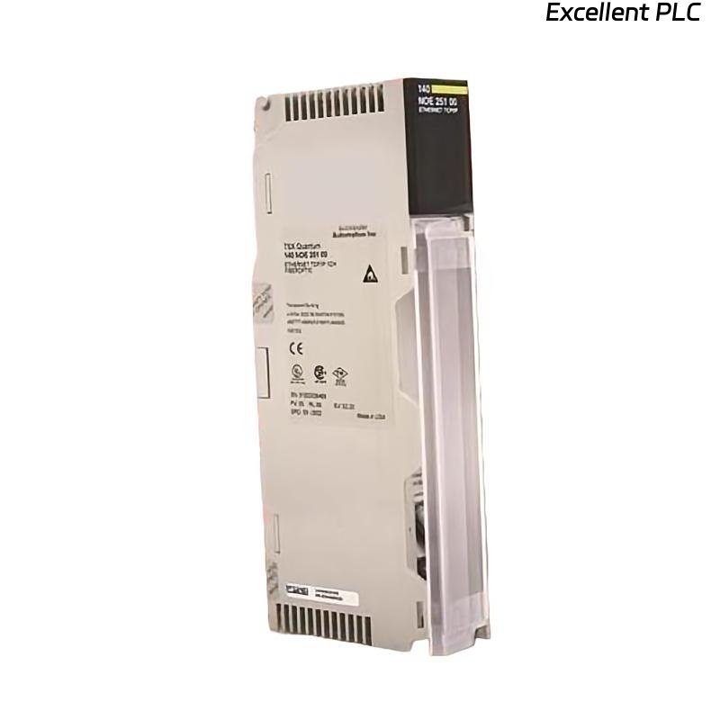
During a recent PLC upgrade for a Modicon Quantum automation system, the Schneider 140NOE25110C Ethernet TCP/IP module was installed to replace an older 140NOE21110C version.
This document summarizes the installation procedure, configuration highlights, and field observations gathered during the process.
The purpose is to help other automation professionals perform similar upgrades smoothly, while avoiding common pitfalls encountered in the field.
⚙️ Hardware Overview
| Parameter | Details |
|---|---|
| Model | Schneider Electric 140NOE25110C |
| Function | Ethernet TCP/IP Communication for Quantum PLC |
| Port Type | RJ-45 10/100 Base-T |
| Protocol Support | Modbus TCP, Ethernet IP, Global Data |
| Power Source | Via PLC backplane (5 V DC) |
| Indicators | RUN, ERR, ACT, LINK LEDs |
🧠 Note: Compared with 140NOE21110C, the 25110C offers enhanced memory, higher throughput, and better support for redundant architectures.
🧰 Installation Environment
-
PLC Rack: Quantum 10-slot
-
Slot Assigned: Position 5 (between CPU 140CPU67160 and 140CHS11000)
-
Power Supply: 140CPS11420
-
Network Equipment: Managed industrial Ethernet switch (Schneider ConneXium)
-
Cabling: Shielded CAT6 cable, 3 m length, RJ-45 terminated
All installation steps were executed with full power isolation and ESD protection.
🔧 Step-by-Step Installation Procedure
Step 1 – Power Isolation
Ensure complete system shutdown. Wait at least 15 seconds after turning off the main PLC power to allow capacitor discharge.
Step 2 – Module Insertion
-
Identify the assigned rack slot.
-
Align the 140NOE25110C with the guide rails.
-
Gently slide the module until it clicks into the backplane connector.
-
Secure the locking screw.
⚠️ Avoid lateral force on the module—bent pins can cause communication failure across the backplane bus.
Step 3 – Network Connection
Connect the Ethernet port to the ConneXium switch using a shielded CAT6 cable.
Ensure the cable shield is properly grounded on both ends to minimize electromagnetic interference.
🖥️ Software Configuration
Configuration was performed via EcoStruxure Control Expert v15.1:
-
Launch project → “Rack Configuration” → select slot 5.
-
Add module 140NOE25110C from hardware catalog.
-
In Module Properties, set:
-
IP Address:
192.168.10.50 -
Subnet Mask:
255.255.255.0 -
Gateway:
192.168.10.1
-
-
Assign Modbus TCP Node ID if needed.
-
Apply configuration and download to PLC.
-
Observe RUN LED (should remain green).
💡 Tip: Always reserve fixed IPs for PLC modules to prevent DHCP conflicts, especially in redundant control systems.
🔍 LED Status Reference
| LED | Color | State | Interpretation |
|---|---|---|---|
| RUN | Green | ON | Module operating normally |
| ERR | Red | OFF | No error |
| ERR | Red | Flashing | Configuration or IP conflict |
| LINK | Green | ON | Physical network link OK |
| ACT | Yellow | Flashing | Active data transmission |
If ERR LED flashes after configuration, verify that the subnet and gateway parameters match the plant network design.
🧪 Communication Verification
After configuration, several validation tests were conducted:
| Test | Tool | Expected Result | Outcome |
|---|---|---|---|
| Ping test | Windows CMD | TTL response < 1 ms | ✅ Passed |
| Modbus TCP read/write | ModScan 64 | Registers 40001–40010 accessible | ✅ Passed |
| PLC Online Connection | Control Expert | Live update and diagnostics active | ✅ Passed |
| Network Load Test | Wireshark Monitor | No packet loss detected | ✅ Passed |
🧰 Field Observations
-
The module booted faster (~8 s) compared with older NOE versions.
-
Under continuous data polling (30 tags/s), CPU load increased only 3 %.
-
Shielded cable grounding effectively reduced packet retry rates from 5 % to 0 %.
-
Operating temperature measured ≈ 36 °C — within manufacturer specification.
🧩 Troubleshooting Insights
| Symptom | Likely Cause | Recommended Action |
|---|---|---|
| No LINK light | Cable not seated or switch offline | Reconnect and recheck switch port |
| ERR LED solid red | Module mismatch in configuration | Re-add correct model in software |
| Cannot connect from Control Expert | Firewall blocking TCP 502 | Temporarily disable or whitelist IP |
| Intermittent communication | High EMI environment | Verify shield grounding, use ferrite rings |
🧾 Maintenance Recommendations
-
Inspect Ethernet connectors quarterly for oxidation.
-
Keep firmware updated via Schneider’s official portal.
-
Label each Ethernet cable with module and port ID.
-
Back up module configuration before every system upgrade.
✅ Summary
The Schneider 140NOE25110C installation was completed successfully and integrated seamlessly with the Quantum PLC system.
Its improved throughput and enhanced diagnostic capability make it an excellent upgrade choice for modern Ethernet-based industrial control systems.
🔧 Engineer’s Note: “In Ethernet-enabled PLC systems, stability begins with clean installation—power, grounding, and IP discipline matter more than anything else.”