

Recently, I performed an installation of the Bently Nevada 3500/25-01-00 vibration monitoring module on a centrifugal compressor in a refinery. This module is part of the 3500 series rack system and is designed to interface with eddy-current proximity probes for precise rotor monitoring. Below is my field-tested step-by-step process.
Step 1: Safety and Preparation
-
Ensure the 3500 rack is powered down and isolated from AC/DC sources.
-
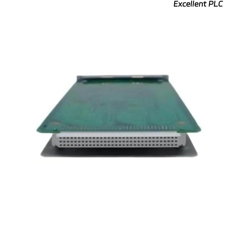
Verify the module part number: 3500/25-01-00.
-
Inspect the module for physical damage, connector cleanliness, and ESD safety.
-
Gather tools: torque screwdriver, multimeter, ESD wrist strap, and cable labeling markers.
Safety tip: Even brief static discharge can damage the analog front end of the module.
Step 2: Physical Mounting
-
Identify the correct slot in the 3500 rack.
-
Slide the module into the DIN rail guides carefully.
-
Lock it in place until it clicks firmly.
-
Verify that front LEDs are off before powering up.
Step 3: Wiring the Module
The 3500/25-01-00 module receives signals from eddy-current probes. Accurate wiring ensures proper vibration monitoring:
| Terminal | Function | Notes |
|---|---|---|
| IN+ | Probe signal | Connect inner conductor of probe cable |
| IN– | Probe return | Connect probe return conductor |
| SG | Shield/ground | Maintain shield continuity from probe tip to module |
| Optional PE | Protective Earth | Connect to chassis ground if available |
Wiring Steps:
-
Strip the probe cable carefully: 8–10 mm of outer insulation and 2–3 mm of inner conductor.
-
Twist the shield braid neatly.
-
Connect signal, return, and shield to their respective terminals.
-
Tighten to recommended torque (~0.4–0.5 Nm).
Field tip: Improper shield connections are the most common cause of noise or intermittent signal faults.
Step 4: Power-Up and LED Verification
-
Apply power to the rack.
-
Observe module LEDs:
-
Green PWR – Power OK
-
Yellow WARN – Signal anomaly or minor fault
-
Red FAULT – Major signal loss or internal error
-
If LEDs indicate fault, double-check cable polarity, shield, and connections.
Step 5: Software Configuration
-
Assign the module to the correct channel in 3500 system software.
-
Define the probe type, alarm thresholds, and sampling rate.
-
Verify communication with the central monitoring station.
Step 6: Field Verification with Example Code
I usually implement a small IEC 61131-3 Structured Text routine to verify module input:
-
This logic continuously monitors vibration amplitude.
-
If the value goes outside operational limits, the alarm is raised.
-
Logging the first readings establishes a baseline for predictive maintenance.
Step 7: Common Field Issues
-
Wrong channel assignment → signal appears missing in software.
-
Loose or reversed connections → FAULT LED or negative readings.
-
Broken shield continuity → noisy data or intermittent alarms.
-
Power sequence errors → module may fail to initialize.
Step 8: Best Practices
-
Label all cables and record channel number, module serial, and probe ID.
-
Capture baseline vibration readings immediately after installation.
-
Route cables carefully to prevent mechanical stress and EMI interference.
-
Maintain a spare module for quick replacement if needed.
Field Takeaways
-
Correct wiring, shielding, and torque application are crucial for reliable operation.
-
Field verification with software and simple code ensures early detection of anomalies.
-
Proper documentation saves time during future maintenance or troubleshooting.
“Precision monitoring is only as reliable as the installation behind it — every wire, every connection, every signal matters.”