

Fault Overview
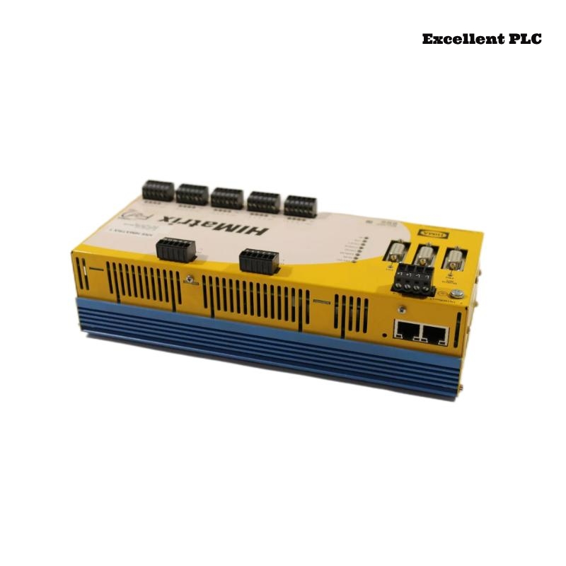
In a HIMatrix safety control network, the Black Horse F2 DO 8 01 Safety-Related Controller experienced intermittent communication loss with the supervisory system.
Observed symptoms:
-
Controller periodically disappears from network
-
Ping response lost for 5–20 seconds
-
No SAFE state triggered
-
Outputs continue operating
-
Link LED flickers during dropout
This indicated communication-layer instability rather than controller crash.
Understanding HIMatrix Network Architecture
The F2 DO 8 01 typically supports:
-
Industrial Ethernet communication
-
Redundant network configuration (optional)
-
Integrated PHY transceiver
-
Watchdog-supervised network stack
If physical layer integrity is compromised, communication drops without affecting safety logic.
Step 1 – Verify Network Infrastructure
1. Inspect Ethernet cable integrity.
2. Replace patch cable.
3. Verify switch port status.
4. Check port error counters.
Cable replacement temporarily reduced dropout frequency but did not eliminate it.
Switch logs showed CRC errors increasing over time.
Step 2 – Measure Ground Potential Difference
Large industrial systems often suffer from grounding inconsistencies.
1. Measure voltage between controller ground and switch ground.
2. Observe during heavy equipment startup.
Detected ground fluctuation of 2–3V during nearby VFD startup.
This level of disturbance can destabilize Ethernet PHY layer.
Step 3 – EMI Susceptibility Test
1. Route temporary shielded Ethernet cable externally.
2. Separate from power cables.
3. Observe link stability.
With shielded isolated routing, communication stabilized completely.
Root Cause – Electromagnetic Interference and Improper Shield Termination
Investigation revealed:
-
Ethernet cable routed parallel to motor power cable
-
Shield not properly grounded at cabinet entry
-
High-frequency noise coupling into twisted pairs
Industrial EMI caused physical layer CRC errors, triggering link renegotiation.
Why Safety Outputs Remained Active
Because:
-
Safety logic runs independently of Ethernet
-
Network stack supervised separately
-
No internal CPU reset occurred
Communication failure did not affect control execution.
Step 4 – Verify PHY Layer Stability
1. Access controller diagnostics.
2. Monitor link negotiation events.
3. Check packet error statistics.
Before correction: frequent link renegotiation events logged.
After correction: stable link, zero CRC increments.
Corrective Action Plan
– Replace with shielded industrial Ethernet cable.
– Implement proper shield grounding at one end.
– Maintain minimum 20 cm separation from power cables.
– Install ferrite cores near cable entry.
After implementing EMC corrections, communication remained stable under all load conditions.
Engineering Best Practices
-
Follow EMC-compliant cabinet wiring standards.
-
Separate power and signal cables physically.
-
Use industrial-grade managed switches.
-
Periodically monitor network error counters.
Industrial Ethernet reliability depends heavily on grounding and cable routing.
Conclusion
Intermittent communication loss on the Black Horse F2 DO 8 01 Safety-Related Controller is frequently caused by EMI-induced physical layer instability rather than controller malfunction. Proper cable routing, shielding, and grounding restore reliable HIMatrix system communication without hardware replacement.