

Article Outline
- Observed Fault Behavior
- Environmental and Electrical Factors
- Diagnostic Checklist for Engineers
- Controller-Level Analysis
- Corrective Repair Procedure
- Preventive Maintenance Strategy
Observed Fault Behavior
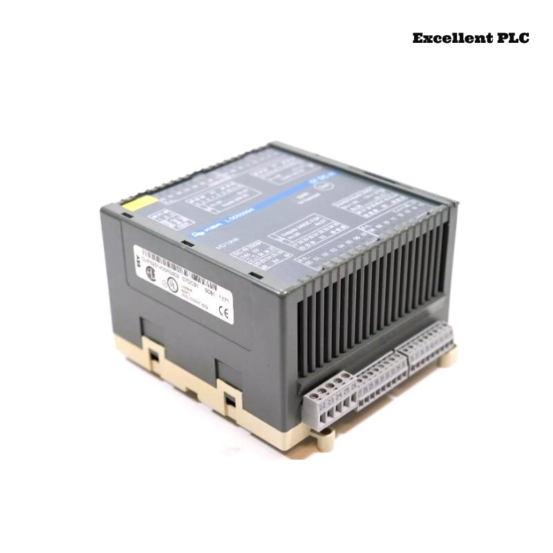
The ABB 07DC91 module (GJR5251400R0202 / GJR5251400R3202) is part of ABB PLC automation systems and participates in digital control communication inside the rack structure. When the module develops operational problems, the automation system may show unusual behavior.
Typical field symptoms include:
- The controller reports that the module cannot be detected.
- Intermittent communication errors inside the rack.
- Unexpected PLC alarms related to hardware configuration.
- Automation sequences stop responding to digital commands.
- Status LEDs on the module remain off or display abnormal patterns.
These problems often appear during system startup, after maintenance work, or when environmental conditions change inside the control cabinet.
Environmental and Electrical Factors
Industrial control cabinets are exposed to a variety of environmental influences that can affect electronic modules. The following conditions frequently contribute to hardware faults.
- Condensation forming inside the cabinet due to temperature changes.
- Electrical noise generated by nearby motors or variable frequency drives.
- Power supply instability or voltage spikes.
- Accumulated dust causing poor contact between connectors.
- Mechanical vibration loosening the module in the rack.
In many cases, the root cause is not the module itself but the installation environment.
Diagnostic Checklist for Engineers
When troubleshooting the 07DC91 module, engineers should follow a systematic inspection process.
Step A – Physical Inspection
- Verify that the module is fully seated in the rack.
- Inspect the front panel for damage or burn marks.
- Confirm that rack ventilation fans are operating.
Step B – Backplane Connector Examination
- Power down the control cabinet.
- Remove the module carefully.
- Check the backplane connector for bent or oxidized pins.
- Clean the connector using approved electronic contact cleaner.
Step C – Power Supply Verification
- Measure the rack power supply voltage.
- Confirm that the supply remains stable during system startup.
- Check grounding continuity between the rack and cabinet frame.
Controller-Level Analysis
Most ABB PLC platforms provide system diagnostics that can help identify module-related issues. Engineers can use maintenance commands to inspect system status.
SYSTEM_STATUS
READ_HARDWARE_CONFIGURATION
SCAN_RACK
CHECK_MODULE 07DC91
READ_EVENT_LOG
Diagnostic information helps determine whether the controller is communicating with the module or if the hardware connection has failed.
Corrective Repair Procedure
After identifying the fault source, the following corrective actions may restore normal operation.
- Reinstall the module to ensure proper backplane connection.
- Replace damaged wiring or connectors.
- Stabilize cabinet power supply using proper industrial power conditioning.
- Improve cabinet ventilation if overheating is detected.
- Install a replacement module when hardware failure is confirmed.
Always verify that the replacement hardware matches the required part numbers GJR5251400R0202 or GJR5251400R3202.
Preventive Maintenance Strategy
Regular maintenance can significantly reduce hardware failures in industrial automation systems.
- Inspect rack connectors during scheduled maintenance.
- Maintain stable cabinet temperature and humidity.
- Check grounding connections periodically.
- Review PLC diagnostic logs for early warning signals.
- Document all module replacements and maintenance activities.
Implementing these preventive measures helps extend the operational life of ABB control modules such as the 07DC91 and improves the reliability of PLC automation systems.