

Table of Contents
- Bently Nevada 146055-05-02-05 Reverse Mount Probe Troubleshooting Entry
- Typical Fault Symptoms of Reverse Mount Probes
- Fault Diagnosis Thinking Based on Signal Behavior
- Common Root Causes in Reverse Installation
- Real Case: Incorrect Orientation Causing Signal Error
- Corrective Actions and System Recovery
- FAQ
- Technical Summary
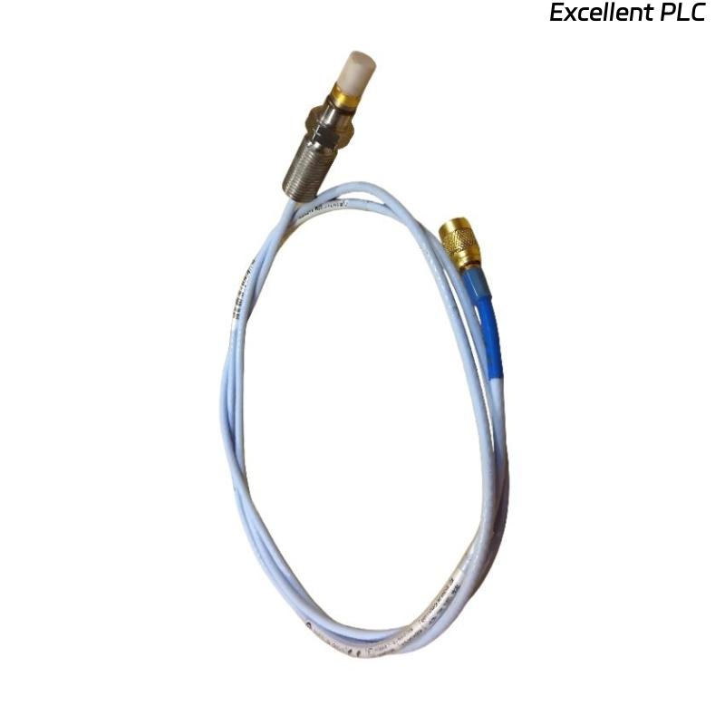
Bently Nevada 146055-05-02-05 Reverse Mount Probe Troubleshooting Entry
Bently Nevada 146055-05-02-05 reverse mount proximity probe troubleshooting shows that abnormal voltage output is frequently caused by incorrect installation direction or gap misalignment rather than probe failure.
This guide provides a structured troubleshooting method focused on reverse mounting characteristics.
Typical Fault Symptoms of Reverse Mount Probes
- Voltage out of expected range
- Inverted or inconsistent signal
- Unstable vibration readings
- No signal detected
These issues often originate from installation conditions.
Fault Diagnosis Thinking Based on Signal Behavior
IF voltage too low or high:
    check probe orientation
    verify gap setting

IF signal inverted:
    inspect installation direction
    confirm system configuration

IF unstable signal:
    check mounting stability
    inspect ceramic tip condition

IF no signal:
    verify connections
    test cable continuity
This logic helps quickly identify installation-related faults.
Common Root Causes in Reverse Installation
- Incorrect probe orientation
- Improper gap adjustment
- Damage to ceramic probe tip
- Loose mounting structure
- Cable or connector issues
Real Case: Incorrect Orientation Causing Signal Error
In a gas compressor system, probe output showed inconsistent voltage fluctuating between -4V and -7V.
Analysis:
- No cable or module issue detected
- Probe installed in reverse orientation
Root Cause: Incorrect mounting direction affecting sensing field.
Solution:
- Reinstalled probe with correct orientation
- Re-adjusted gap
Result: Voltage stabilized at -8.5V with consistent vibration signal.
Corrective Actions and System Recovery
- Reinstall probe with correct direction
- Calibrate gap during commissioning
- Inspect ceramic tip for damage
- Ensure stable mounting conditions
Always verify system performance after corrective action.
FAQ
Why does reverse probe show abnormal voltage?
This is usually due to incorrect installation direction or gap setting.
Can ceramic tip damage affect measurement?
Yes, damage will significantly impact signal quality.
Is troubleshooting different from standard probes?
Yes, reverse mount probes require additional focus on orientation.
Technical Summary
This Troubleshooting Guide demonstrates that Bently Nevada 146055-05-02-05 reverse mount proximity probe faults are mainly related to installation orientation, gap control, and mechanical integrity. Structured fault diagnosis ensures accurate measurement and reliable system operation.