

Table of Contents
- Bently Nevada 177230-00-01-05 Installation Guide Entry
- Role of Seismic Sensor in Vibration Monitoring Systems
- Mounting Strategy and Mechanical Coupling
- 4–20 mA Loop Wiring and PLC Integration
- Typical Installation Errors and Prevention
- Commissioning and Signal Verification
- FAQ
- Technical Summary
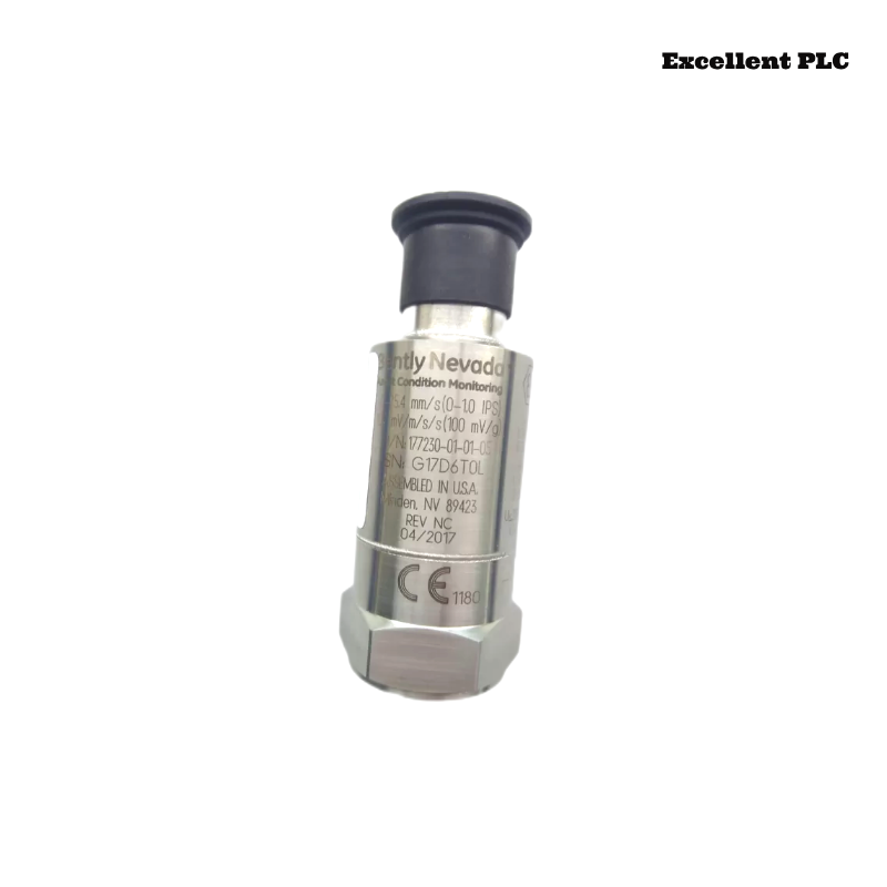
Bently Nevada 177230-00-01-05 Installation Guide Entry
Bently Nevada 177230-00-01-05 seismic sensor installation issues are most often caused by poor mechanical coupling or incorrect 4–20 mA loop wiring, resulting in low or unstable vibration signals rather than sensor failure.
This Installation Guide focuses on achieving accurate vibration transmission and stable current loop integration.
Role of Seismic Sensor in Vibration Monitoring Systems
- Measures casing vibration instead of shaft displacement
- Outputs 4–20 mA signal proportional to vibration velocity
- Integrates directly with PLC or monitoring modules
The sensor supports loop-powered operation and provides reliable vibration data for condition monitoring systems. :contentReference[oaicite:0]{index=0}
Mounting Strategy and Mechanical Coupling
- Install sensor on rigid machine surface (bearing housing preferred)
- Ensure flat, clean mounting surface
- Use proper torque to avoid loosening
- Avoid mounting on thin covers or flexible structures
IF vibration reading too low:
    check mounting rigidity
    verify sensor firmly coupled

IF signal noisy:
    inspect mechanical looseness
Engineering Insight: Poor mechanical coupling attenuates vibration energy before reaching the sensor.
4–20 mA Loop Wiring and PLC Integration
- Power supply: typically 12–48 VDC loop-powered
- Output signal: 4–20 mA or 1–5V depending on configuration
- Connect to PLC analog input module
IF no signal:
    check loop continuity
    verify supply voltage

IF signal stuck at 4 mA:
    sensor not detecting vibration or wiring issue

IF signal unstable:
    check grounding and shielding
Proper loop configuration ensures accurate data transmission to PLC systems.
Typical Installation Errors and Prevention
- Mounting sensor on non-rigid surfaces
- Incorrect polarity in current loop
- Routing signal cables near high-power lines
Real Case:
In a pump monitoring system, vibration readings remained below 1 mm/s despite visible mechanical vibration. Investigation showed sensor mounted on a thin inspection cover. After relocating to bearing housing, reading increased to 4.3 mm/s, matching expected values.
Commissioning and Signal Verification
- Verify baseline signal (~4–6 mA under low vibration)
- Observe signal during machine startup
- Compare readings with portable vibration analyzer
Commissioning confirms system accuracy and reliability.
FAQ
Why is vibration reading too low?
This is usually caused by poor mounting or incorrect installation location.
Can the sensor connect directly to PLC?
Yes, via 4–20 mA analog input.
What is the typical power supply?
Usually 12–48 VDC loop-powered operation.
Technical Summary
This Installation Guide shows that Bently Nevada 177230-00-01-05 sensor performance depends on proper mechanical mounting, correct loop wiring, and stable system configuration. Accurate installation ensures reliable vibration monitoring in industrial applications.