

Table of Contents
- Bently Nevada 170133-XXX-00 Installation Guide Entry
- Impact of XXX Option on Installation Strategy
- Probe System Matching and Length Configuration
- Mechanical Installation and Rack Integration
- Signal Validation and Output Verification
- Commissioning Under Real Operating Conditions
- FAQ
- Technical Summary
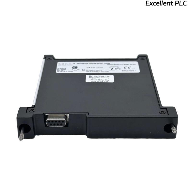
Bently Nevada 170133-XXX-00 Installation Guide Entry
Bently Nevada 170133-XXX-00 dual proximitor module installation errors are most commonly caused by incorrect probe system length selection (5m / 9m / 14m) rather than module hardware failure, leading to non-linear signal output or inaccurate vibration readings.
This Installation Guide focuses on correct system matching and flexible configuration across different XXX variants.
Impact of XXX Option on Installation Strategy
The “XXX” in the model defines total system length and directly affects calibration and signal scaling.
- 050 → 5-meter system
- 090 → 9-meter system
- 140 → 14-meter system
Engineering Insight: Mixing different system lengths in dual channels introduces hidden measurement errors even if signals appear normal.
Probe System Matching and Length Configuration
- Ensure probe + extension cable length matches module calibration
- Use identical lengths for both channels in dual configurations
- Verify compatibility with 5 mm or 8 mm probe systems
Incorrect matching results in distorted signal linearity.
Mechanical Installation and Rack Integration
- Insert module into designated 3300 rack slot
- Align carefully with backplane connector
- Avoid tilting during insertion
- Secure module firmly to prevent vibration-induced loosening
Stable mechanical installation ensures reliable electrical connection.
Signal Validation and Output Verification
- Measure output voltage range (-1V to -17V typical)
- Verify linear response across probe displacement range
- Ensure both channels show consistent baseline voltage (~ -9V)
IF signal nonlinear:
    check system length match
    verify calibration option (XXX)

IF voltage out of range:
    adjust probe gap
    inspect probe condition

IF channel mismatch:
    compare both probe systems
    verify identical configuration
Real Case:
In a steam turbine installation, one channel used a 5m system while the module was configured for 9m (090). Output voltage fluctuated between -3V and -6V instead of stable -9V. After correcting to a 9m matched system, voltage stabilized at -9.2V and vibration readings became accurate.
Commissioning Under Real Operating Conditions
- Check signal stability during machine startup
- Monitor both channels under load changes
- Compare readings with baseline vibration signature
Commissioning validates full system configuration.
FAQ
What does the XXX code mean?
It defines system length and calibration of the proximitor module.
Can different lengths be used on two channels?
Technically possible, but strongly discouraged due to measurement inconsistency.
Why is the output voltage not around -9V?
This is usually due to incorrect probe gap or system length mismatch.
Technical Summary
This Installation Guide highlights that Bently Nevada 170133-XXX-00 module performance depends heavily on correct system length matching, proper installation, and accurate configuration. The XXX option must always align with probe system design to ensure reliable monitoring.