

Table of Contents
- Bently Nevada 177230-00-01-05 Troubleshooting Entry
- Typical 4–20 mA Signal Fault Symptoms
- Fault Diagnosis Logic for Seismic Sensors
- Common Causes of Sensor Signal Failure
- Real Case: False Low Vibration Reading
- Recovery Strategy and Optimization
- FAQ
- Technical Summary
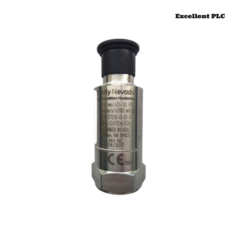
Bently Nevada 177230-00-01-05 Troubleshooting Entry
Bently Nevada 177230-00-01-05 seismic sensor troubleshooting shows that abnormal 4–20 mA signals—such as constant 4 mA, fluctuating output, or incorrect vibration values—are typically caused by installation issues, loop wiring problems, or environmental factors rather than sensor hardware failure.
This guide provides a structured fault diagnosis approach based on current loop behavior.
Typical 4–20 mA Signal Fault Symptoms
- Signal fixed at 4 mA (no vibration detection)
- Signal fluctuating under steady conditions
- Output saturated near 20 mA
- Intermittent signal loss
Each symptom indicates a specific fault type.
Fault Diagnosis Logic for Seismic Sensors
IF 4 mA constant:
    check sensor mounting
    verify loop continuity

IF signal fluctuates:
    inspect grounding
    check EMI interference

IF signal high (near 20 mA):
    check sensor overload
    verify scaling configuration

IF intermittent signal:
    inspect connectors
    check power stability
This logic helps isolate issues efficiently in field conditions.
Common Causes of Sensor Signal Failure
- Poor mechanical coupling reducing vibration transmission
- Incorrect loop wiring or polarity
- Power supply instability
- Electromagnetic interference from nearby equipment
Real Case: False Low Vibration Reading
In a blower system, vibration reading stayed at 4–5 mA despite increasing load.
Observed Data:
- No change in current signal during load variation
- Portable analyzer showed 5.2 mm/s vibration
Analysis: Sensor not properly coupled to vibration source.
Root Cause: Loose mounting bolt causing poor vibration transmission.
Solution:
- Re-tightened sensor with proper torque
- Re-mounted on rigid surface
Result: Signal increased to 10–14 mA range, matching actual vibration.
Recovery Strategy and Optimization
- Ensure rigid mechanical mounting
- Maintain proper loop wiring and polarity
- Use shielded cables and proper grounding
- Perform periodic signal verification
Consistent maintenance ensures reliable monitoring performance.
FAQ
Why is the signal always 4 mA?
This indicates no vibration detection or wiring issue.
How to verify sensor accuracy?
Compare with a portable vibration analyzer.
Is sensor failure common?
No, most issues are related to installation or wiring.
Technical Summary
This Troubleshooting Guide demonstrates that Bently Nevada 177230-00-01-05 sensor faults are mainly caused by installation and loop wiring issues. A structured fault diagnosis approach ensures accurate and stable vibration monitoring.