

Table of Contents
- Bently Nevada 177230-02-01-CN Installation Guide Entry
- 177230-02-01-CN Seismic Sensor Role in PLC/DCS Systems
- Installation Logic for High-Range Hazardous Applications
- 4–20 mA Loop Design and System Configuration
- Hazardous Area Installation Control Points
- Commissioning and Signal Validation Strategy
- FAQ
- Technical Summary
Bently Nevada 177230-02-01-CN Installation Guide Entry
Bently Nevada 177230-02-01-CN seismic sensor installation failures are typically caused by improper mechanical coupling or incorrect hazardous area wiring, leading to distorted 4–20 mA output rather than actual sensor damage.
This Installation Guide focuses on high-range vibration monitoring combined with CN hazardous approvals, where both signal integrity and safety compliance are critical.
177230-02-01-CN Seismic Sensor Role in PLC/DCS Systems
- Measures vibration velocity up to 50.8 mm/s (high-range)
- Provides loop-powered 4–20 mA output
- Offers dynamic signal output for advanced diagnostics
- Supports PLC, DCS, and SCADA integration
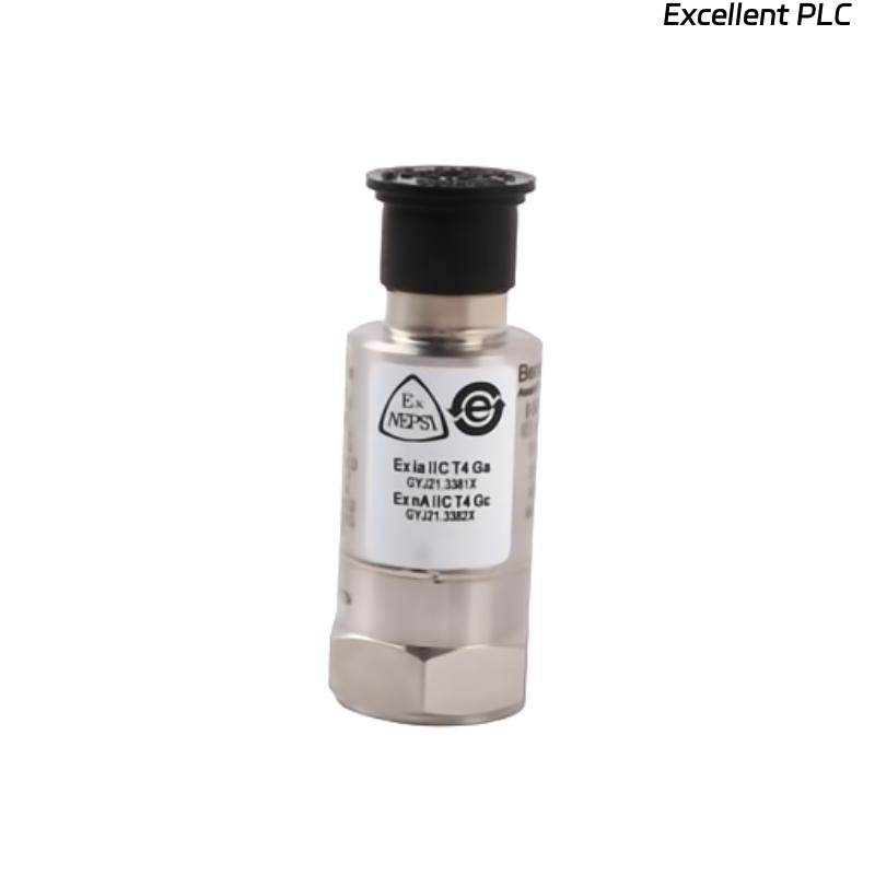
This model is designed for hazardous environments with CN (NEPSI/ATEX-equivalent) approvals and robust stainless steel construction. :contentReference[oaicite:0]{index=0}
Installation Logic for High-Range Hazardous Applications
Installation must follow vibration transmission physics and hazardous area constraints simultaneously:
- Select rigid mounting point (bearing housing only)
- Remove paint layer to ensure metal-to-metal contact
- Use 1/4-28 UNF mounting thread
- Apply controlled torque to prevent micro-looseness
IF signal amplitude too low:
    check mounting stiffness
    verify vibration path

IF signal distorted:
    check mechanical resonance or loose interface
Engineering Insight: In high-range sensors, mounting error introduces non-linear distortion, especially above 30 mm/s vibration.
4–20 mA Loop Design and System Configuration
- Power supply: 12–30 VDC (loop-powered)
- Output: 4–20 mA proportional to vibration velocity
- Additional raw signal output for verification
IF current = 0 mA:
    check power supply and loop continuity

IF signal stuck at 4 mA:
    insufficient vibration or wrong installation point

IF signal saturates early:
    PLC scaling mismatch
The sensor integrates easily with PLC analog input modules without requiring field calibration. :contentReference[oaicite:1]{index=1}
Hazardous Area Installation Control Points
- Use certified intrinsic safety barriers
- Ensure cable glands meet IP67 sealing requirements
- Avoid mixed grounding systems
- Use shielded cables with single-point grounding
Real Case:
In a refinery compressor system, vibration signal fluctuated between 6–18 mA despite stable operation.
Observed:
- Fluctuation increased during humidity changes
Root Cause: Non-certified cable gland causing moisture ingress.
Solution:
- Replaced with certified hazardous area gland
- Improved sealing and grounding
Result: Signal stabilized at 9–13 mA, consistent with vibration level (~20 mm/s).
Commissioning and Signal Validation Strategy
- Verify baseline (~4–6 mA at idle)
- Monitor signal during load ramp
- Cross-check with handheld vibration analyzer
Commissioning Tip: Perform validation after thermal stabilization to avoid false drift.
FAQ
What does CN approval mean?
It refers to country-specific hazardous area certification (e.g., NEPSI/ATEX compliance).
Why is the signal unstable in humid environments?
Moisture ingress or improper sealing can affect signal integrity.
Can this sensor be used directly with PLC systems?
Yes, it provides a standard 4–20 mA signal compatible with PLC inputs.
Technical Summary
This Installation Guide shows that Bently Nevada 177230-02-01-CN performance depends on rigid mechanical installation, proper hazardous area compliance, and correct system configuration. Accurate installation ensures reliable high-range vibration monitoring in critical industrial environments.