

Table of Contents
- Bently Nevada 177230-02-02-05 Installation Guide Entry
- 177230-02-02-05 Seismic Sensor Role in Monitoring Systems
- Installation Strategy Based on Frequency and Range
- 4–20 mA Loop Setup and PLC Configuration
- Installation Risk Analysis in High-Vibration Equipment
- Commissioning and Signal Validation
- FAQ
- Technical Summary
Bently Nevada 177230-02-02-05 Installation Guide Entry
Bently Nevada 177230-02-02-05 seismic sensor installation issues are most often caused by incorrect frequency-range application or poor mounting stiffness, leading to distorted vibration signals rather than sensor malfunction.
This Installation Guide focuses on high-range and wide-frequency vibration monitoring systems where signal fidelity depends heavily on installation quality.
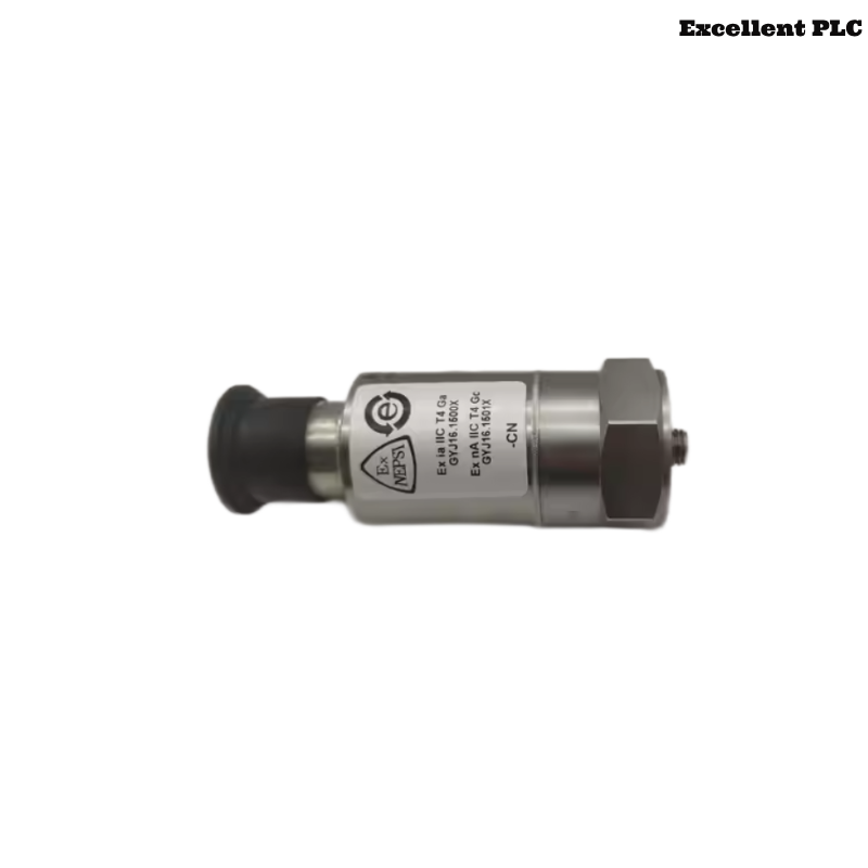
177230-02-02-05 Seismic Sensor Role in Monitoring Systems
- Measurement range: up to 50.8 mm/s
- Frequency response: 3 Hz to 1 kHz
- Output: 4–20 mA loop-powered signal
- Compatible with PLC, DCS, and 3500 monitoring systems
This model is optimized for medium-to-low frequency machinery vibration such as turbines, compressors, and large fans. :contentReference[oaicite:0]{index=0}
Engineering Insight: Frequency selection (Option 02) directly impacts installation location and signal interpretation.
Installation Strategy Based on Frequency and Range
The 3 Hz–1 kHz frequency band requires attention to structural resonance and mounting location:
- Install near bearing housing to capture fundamental vibration
- Avoid thin plates or covers that attenuate low-frequency signals
- Ensure flat, clean mounting surface
- Apply 4–7 N·m torque for stable coupling
IF low-frequency signal missing:
    mounting location too flexible

IF high-frequency noise present:
    structural resonance or loose installation
Field Observation: Low-frequency vibration (<10 Hz) is easily lost if installation is not directly on structural mass.
4–20 mA Loop Setup and PLC Configuration
- Power supply: 12–30 VDC
- Signal: 4–20 mA proportional to velocity
- Optional dynamic output for advanced diagnostics
IF signal stuck at 4 mA:
    no vibration or incorrect installation

IF signal saturates early:
    PLC scaling mismatch

IF signal noisy:
    grounding or EMI issue
The sensor integrates seamlessly into industrial control systems via standard analog input modules. :contentReference[oaicite:1]{index=1}
Installation Risk Analysis in High-Vibration Equipment
- Incorrect installation point (non-structural area)
- Improper torque causing micro-movement
- Frequency mismatch with application
- Poor cable shielding introducing noise
Real Case:
In a centrifugal compressor, vibration readings remained below 8 mA despite visible mechanical vibration.
Observed Data:
- Low-frequency vibration (<10 Hz) not detected
Root Cause: Sensor installed on thin inspection cover.
Solution:
- Relocated sensor to bearing housing
- Re-tightened mounting to specified torque
Result: Signal increased to 10–17 mA, accurately reflecting ~25 mm/s vibration.
Commissioning and Signal Validation
- Check idle output (~4–6 mA)
- Observe signal during load ramp
- Validate with handheld vibration analyzer
Commissioning Tip: Always validate frequency response by comparing with FFT analyzer data.
FAQ
Why is low-frequency vibration not detected?
This is usually caused by installation on flexible structures that damp low-frequency signals.
What is the frequency range of this sensor?
3 Hz to 1 kHz, suitable for most industrial machinery vibration monitoring. :contentReference[oaicite:2]{index=2}
Can it connect directly to PLC systems?
Yes, via standard 4–20 mA analog input modules.
Technical Summary
This Installation Guide shows that Bently Nevada 177230-02-02-05 performance depends on correct frequency-based installation strategy, rigid mounting, and proper system configuration. Accurate installation ensures reliable vibration monitoring across a wide frequency range.