

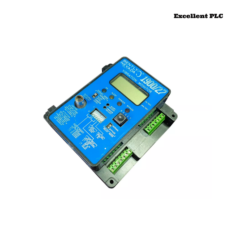
Bently Nevada 1900/27-03 Vibration Monitor Installation Guide Based on Field Commissioning Log and System Configuration Decisions
Table of Contents
- Initial Installation Condition of 1900/27-03 Monitor
- First Signal Reading After Power-Up
- Why the First Reading Was Rejected
- Step-by-Step Adjustment and Configuration Changes
- Final System Configuration and Stable Operation
- 1900/27-03 Installation Lessons from Field
- FAQ
- Technical Summary
Initial Installation Condition of 1900/27-03 Monitor
Bently Nevada 1900/27-03 vibration monitor installation was completed according to wiring diagram. No visible issues were found during inspection.
- Power supply measured: 24.1V DC
- Signal cables properly terminated
- Sensor connected: velocity type (100 mV/mm/s)
At this stage, installation would normally be considered complete.
First Signal Reading After Power-Up
After powering the system:
- Displayed vibration: 65 mm/s
- Machine condition: visually stable
This created immediate doubt — the value was too high for the operating condition.
Why the First Reading Was Rejected
Instead of accepting the reading, we compared it with physical observations:
- No abnormal noise
- No excessive temperature
- No mechanical instability
Conclusion:
installation is electrically correct, but system configuration is not.
Step-by-Step Adjustment and Configuration Changes
STEP 1: verify sensor type
→ confirmed velocity sensor

STEP 2: check monitor input configuration
→ set as proximity (incorrect)

STEP 3: change to velocity mode
→ reading drops significantly

STEP 4: adjust scaling factor
→ align with 100 mV/mm/s

STEP 5: observe stability during operation
After adjustment:
- Reading changed to 28–31 mm/s
Final System Configuration and Stable Operation
Final configuration included:
- Correct sensor input type
- Accurate scaling parameters
- Alarm thresholds adjusted to operational limits
Additional improvement:
- Separated signal cable from motor cable to reduce noise
Final verification:
- Monitor: 29 mm/s
- Portable analyzer: 30 mm/s
1900/27-03 Installation Lessons from Field
- Do not trust first reading without validation
- Always match configuration to sensor type
- Use physical observation to challenge data
- Installation ends only after signal is validated
FAQ
Why does 1900/27-03 show high vibration immediately after installation?
This is often caused by incorrect input configuration or scaling mismatch.
How to confirm installation is correct?
Compare monitor readings with actual machine condition and independent measurement tools.
Technical Summary
Bently Nevada 1900/27-03 installation must be validated through real signal behavior rather than wiring completion. Field commissioning logs show that configuration errors are a primary cause of incorrect readings. A decision-driven installation approach ensures accurate vibration monitoring and reliable system performance.