

Table of Contents
- 200152-04-00 Installation Overview
- Role of 200152-04-00 Accelerometer Interface Cable
- Installation Planning and Risk Assessment
- Cable Routing and EMI Shielding
- Wiring Connections and Signal Integrity
- System Configuration and Calibration
- Commissioning and Signal Validation
- Field Installation Case
- Installation FAQ
- Final Engineering Summary
200152-04-00 Installation Overview
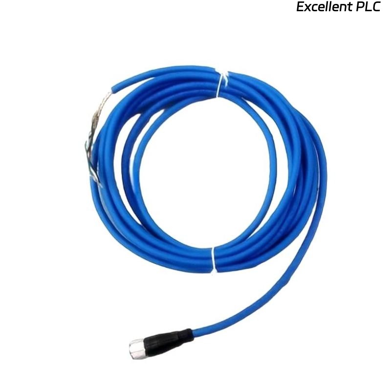
The Bently Nevada 200152-04-00 is an accelerometer interface standard cable designed to connect vibration sensors to the 3500 system. Its reliability directly affects the quality of vibration monitoring in rotating machinery such as turbines, compressors, and pumps.
This guide covers the installation procedures, including wiring, cable routing, and commissioning to ensure accurate sensor-to-monitor signal transmission.
Role of 200152-04-00 Accelerometer Interface Cable
- Transmits analog vibration signals from the accelerometer to the monitoring system
- Supports high-frequency signal transmission with minimal interference
- Used in Bently Nevada’s 3500 machinery monitoring system
- Critical for continuous monitoring and protection of industrial equipment
Installation Planning and Risk Assessment
- Identify the shortest cable path while avoiding sharp bends or physical damage
- Ensure proper cable length for system setup (approximately 10m to 30m typical)
- Consider electromagnetic interference (EMI) from nearby power cables and motors
- Perform risk analysis for cable exposure to environmental factors such as temperature extremes
Cable Routing and EMI Shielding
- Keep the cable at least 300 mm away from high-current cables
- Use cable trays to protect from mechanical damage and reduce EMI exposure
- Route cables away from sources of heat, moisture, or physical abrasion
- Ensure proper shielding grounding to prevent signal distortion
  // EMI Shielding Logic
  IF Noise_Level_High AND Cable_Near_Power THEN
      Re-route_Cable();
  END_IF;
Wiring Connections and Signal Integrity
- Verify correct pinout of connectors before connecting to the accelerometer and monitoring system
- Secure all wiring connections to avoid signal loss or intermittent failures
- For best signal quality, maintain wire resistance within acceptable limits
- Ensure the cable is well insulated and secured against environmental damage
System Configuration and Calibration
- Configure the accelerometer input channel in the monitoring system
- Set appropriate gain and scaling factors for vibration signal transmission
- Define alarm thresholds for the accelerometer readings based on system specifications
- Map input signals to their respective PLC or control system inputs
Commissioning and Signal Validation
- Perform static voltage checks on the accelerometer output before starting the machinery
- Run machinery at low speed and monitor the signal to ensure proper transmission
- Check the system for noise and signal interference using diagnostic tools
- Monitor the signal under full-load conditions to ensure stable readings
Field Installation Case
During a turbine monitoring system installation, the 200152-04-00 cable showed intermittent signal loss under full-load conditions:
- The signal dropped below expected levels at 10m cable length
- Noise spikes occurred in the signal during startup
Upon investigation, the cable was routed too close to a motor feeder line, introducing EMI. After rerouting the cable:
- Signal stability was restored, with a consistent output of 4.1 mV/μm
- No further noise spikes during system startup
Installation FAQ
What is the ideal cable length for 200152-04-00 installation?
The recommended cable length is between 10m to 30m depending on the installation layout and distance to the monitoring system.
Can I use this cable near power cables?
It is best to maintain a 300 mm separation from power cables to avoid electromagnetic interference (EMI).
Is it necessary to ground the cable shielding?
Yes, grounding the shielding at the monitoring system end helps eliminate external interference and ensures clean signal transmission.
Final Engineering Summary
The Bently Nevada 200152-04-00 Installation Guide emphasizes the importance of careful cable routing, proper grounding, and system configuration to maintain signal integrity. By following the correct installation practices, users can ensure long-term, stable operation of their machinery monitoring systems.