

Table of Contents
- 200152-15-00 Installation Overview
- Role of 200152-15-00 Accelerometer Interface Cable
- Installation Planning and Risk Assessment
- Cable Routing and EMI Shielding
- Wiring Connections and Signal Integrity
- System Configuration and Calibration
- Commissioning and Signal Validation
- Field Installation Case
- Installation FAQ
- Final Engineering Summary
200152-15-00 Installation Overview
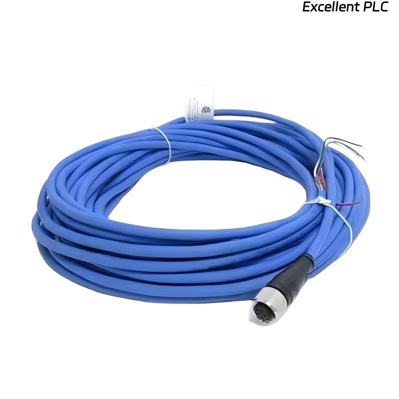
The Bently Nevada 200152-15-00 accelerometer interface standard cable is essential for connecting vibration sensors to the 3500 monitoring system. Ensuring proper installation is critical for obtaining accurate vibration data and minimizing the risk of false readings due to poor signal transmission.
This guide provides detailed instructions for the proper wiring, cable routing, and system calibration, ensuring optimal performance of the accelerometer interface cable.
Role of 200152-15-00 Accelerometer Interface Cable
- Transmits high-fidelity vibration signals from the accelerometer to the monitoring system
- Supports both analog and digital signals with minimal signal loss or distortion
- Ensures reliable and continuous monitoring of machinery such as turbines, compressors, and motors
- Works in tandem with the Bently Nevada 3500 machinery monitoring system
Installation Planning and Risk Assessment
- Identify the best cable routing path, avoiding sharp bends and excessive length
- Account for the environmental factors such as temperature, vibration, and exposure to chemicals
- Consider electromagnetic interference (EMI) and install cable far from high-power equipment
- Perform a risk assessment of cable exposure to abrasion, cuts, or sharp objects
Cable Routing and EMI Shielding
- Keep the cable at least 30 cm away from power cables and high-frequency equipment
- Use proper cable trays or conduits to prevent physical damage
- Ensure the cable is routed away from sources of heat, moisture, or excessive vibration
- Ensure grounding of the shielding at one end to reduce EMI interference
  // EMI Shielding Guidance
  IF Signal_Noise > Threshold THEN
      Check_Cable_Shielding();
  ELSE
      Re-route_Cable_Away_From_EMI();
  END_IF;
Wiring Connections and Signal Integrity
- Ensure proper pinout when connecting to both accelerometer and monitoring system
- Inspect for any loose connections or damaged connectors that might cause signal loss
- Maintain wire resistance within acceptable limits to avoid signal degradation
- Ensure proper insulation and protection against environmental damage
System Configuration and Calibration
- Configure the accelerometer input channel in the 3500 monitoring system
- Set the correct scaling factors for vibration signal readings
- Adjust alarm thresholds for critical vibration levels, based on machine specifications
- Map input signals to PLC or control system inputs for data integration
Commissioning and Signal Validation
- Perform static voltage checks before energizing the system
- Run machinery at low speeds and monitor the signal for consistency and accuracy
- Verify signal integrity using diagnostic equipment such as oscilloscopes
- Test the system under full load conditions to ensure stable operation
Field Installation Case
During a commissioning of a centrifugal compressor, the 200152-15-00 cable exhibited intermittent signal loss:
- The signal dropped during startup
- Oscilloscope confirmed noise spikes during motor operation
After further inspection, it was found that the cable had been routed too close to high-voltage power lines, causing EMI interference. Re-routing the cable resolved the issue:
- Signal stabilized and remained within expected voltage range of -9.8V
- All alarm conditions cleared after cable re-routing
Installation FAQ
What is the recommended cable length for the 200152-15-00?
The recommended cable length for this accelerometer interface cable is between 10m and 30m, depending on the layout and distance from the monitoring system.
Can I route the cable alongside power lines?
It is highly recommended to keep the cable at least 30 cm away from power lines to minimize electromagnetic interference (EMI).
Do I need to ground the cable shielding?
Yes, grounding the shielding at one end of the cable helps prevent EMI interference and ensures signal integrity.
Final Engineering Summary
The Bently Nevada 200152-15-00 Installation Guide emphasizes the importance of careful planning, proper routing, and secure connections. By following these best practices, you ensure the reliability and longevity of your machinery monitoring system, avoiding unnecessary signal interruptions or degradation.