

Table of Contents
- 200200-01-01-05 Installation Overview
- Role of the 200200-01-01-05 Trendmaster proTim-R Module Input
- Installation Planning and Risk Assessment
- Wiring and Connection Guidelines
- System Configuration and Calibration
- Commissioning and Signal Validation
- Field Installation Case
- Installation FAQ
- Final Engineering Summary
200200-01-01-05 Installation Overview
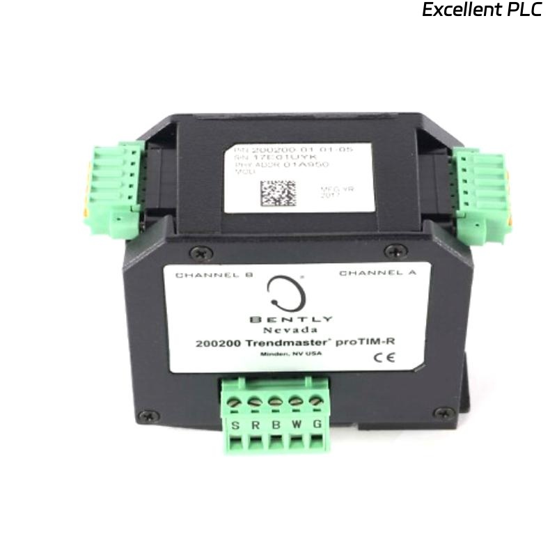
The Bently Nevada 200200-01-01-05 Trendmaster proTim-R module input is designed to interface with vibration sensors, providing accurate measurements for machinery monitoring systems. Proper installation ensures that vibration data is captured accurately and reliably for real-time analysis.
This guide covers the steps for properly installing, wiring, and configuring the 200200 Trendmaster module, ensuring it functions optimally in your machinery protection setup.
Role of the 200200-01-01-05 Trendmaster proTim-R Module Input
- Acts as an input module for connecting vibration sensors to the Trendmaster system
- Collects real-time vibration data from sensors for trend analysis
- Transmits accurate vibration information to the Bently Nevada 3500 system for system-wide monitoring
- Supports critical monitoring applications such as turbines, pumps, and compressors
Installation Planning and Risk Assessment
- Ensure proper placement of the Trendmaster module in the system configuration for easy access and minimal interference
- Perform an environmental risk assessment, considering temperature, humidity, and other site conditions that may affect the system’s performance
- Account for electromagnetic interference (EMI) from nearby equipment, and select proper shielding and grounding techniques
- Plan for secure wiring and connections to avoid signal degradation
Wiring and Connection Guidelines
- Verify correct pinout and connector specifications for the 200200-01-01-05 module and connected sensors
- Ensure all wiring connections are secure, with no loose or damaged connectors
- Minimize cable length to reduce signal loss and interference
- Use shielded cables to protect against electromagnetic interference (EMI)
- Check the system for proper grounding, ensuring that the module and sensors are correctly grounded to prevent noise and instability
  // Wiring Best Practices
  IF Signal_Integrity_Compromised THEN
      Check_Connector_Integrity();
      Inspect_Shielding_Grounding();
  ELSE
      Verify_Wire_Routing_And_Connection();
  END_IF;
System Configuration and Calibration
- Configure the Trendmaster proTim-R module in the monitoring system software
- Set the correct sensor input ranges based on machine specifications
- Adjust the system’s alarm and warning thresholds to reflect the expected vibration limits
- Calibrate the module to ensure accurate readings across the expected operational range of machinery
Commissioning and Signal Validation
- Perform a visual inspection of all connections and verify wiring integrity
- Start the system and verify that the module inputs are receiving proper sensor signals
- Validate the data transmission by checking the module’s output against expected readings
- Monitor the system during various operational conditions to ensure data accuracy and system stability
Field Installation Case
During a routine commissioning of a gas turbine monitoring system, the Bently Nevada 200200-01-01-05 Trendmaster module showed signal inconsistencies:
- The vibration readings appeared erratic during operational tests
- Signal analysis revealed spikes during turbine startup
Upon investigation, it was determined that the wiring had been routed too close to high-voltage power lines, leading to EMI interference. After rerouting the cables and ensuring proper grounding:
- The signal became stable, with consistent vibration readings observed during both idle and full-load operations
- The system alarm thresholds were adjusted accordingly to avoid false alarms
Installation FAQ
What should I do if the signal output appears unstable?
Instability in signal output can be caused by EMI, poor grounding, or improper wiring. First, verify that the wiring is securely connected, and check for any sources of interference nearby. Additionally, ensure the module’s shielding is properly grounded.
How can I reduce the risk of EMI interference?
Minimize cable length, use shielded cables, and route the wiring away from sources of high electromagnetic fields, such as power lines and large motors.
What are the optimal wiring distances for the 200200-01-01-05 module?
To minimize signal degradation, keep wiring as short as possible while ensuring that all components are properly connected. Long cable runs may require signal boosters or repeaters to maintain signal integrity.
Final Engineering Summary
The Bently Nevada 200200-01-01-05 Trendmaster proTim-R Module Input Installation Guide emphasizes the importance of proper system setup, careful wiring, and addressing environmental factors to ensure reliable and accurate vibration data transmission. By following the outlined steps, you ensure optimal performance and data integrity for your machinery monitoring system.