

Table of Contents
- 200152-15-10 Installation Overview
- Role of 200152-15-10 Accelerometer Interface Cable
- Installation Planning and Risk Assessment
- Cable Routing and EMI Shielding
- Wiring Connections and Signal Integrity
- System Configuration and Calibration
- Commissioning and Signal Validation
- Field Installation Case
- Installation FAQ
- Final Engineering Summary
200152-15-10 Installation Overview
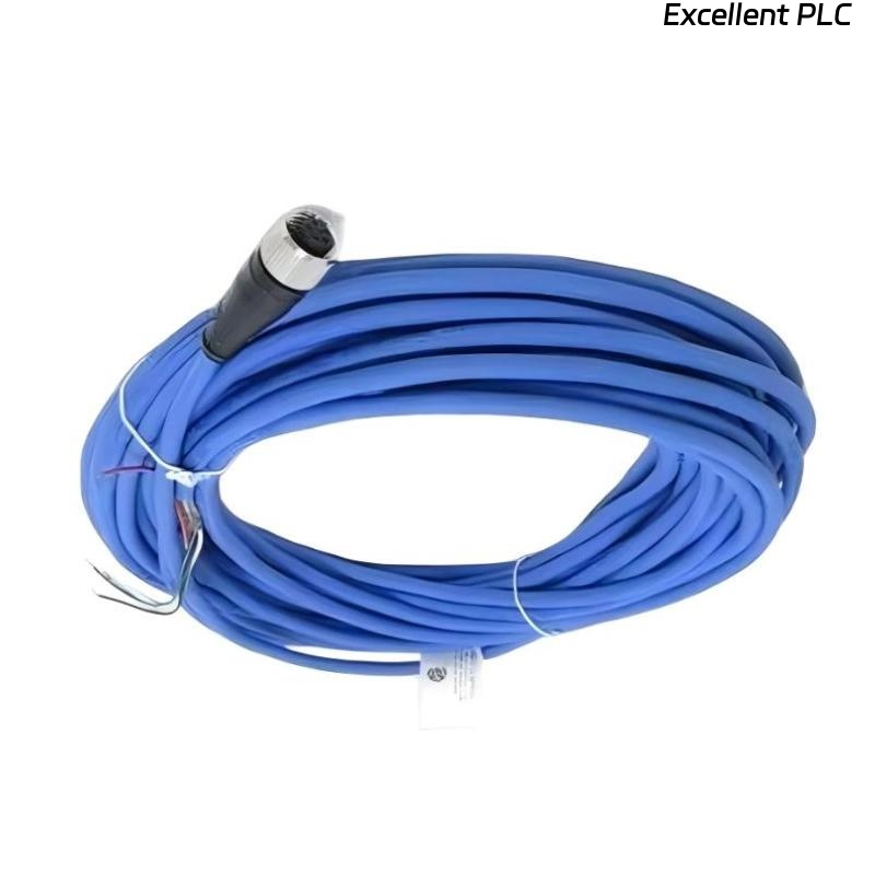
The Bently Nevada 200152-15-10 accelerometer interface standard cable is designed to facilitate the connection between vibration sensors and the 3500 monitoring system. Proper installation ensures high-fidelity vibration data transmission and enables accurate monitoring of rotating machinery.
This guide will take you through the step-by-step process for installing the 200152-15-10 cable, including wiring, routing, and system configuration.
Role of 200152-15-10 Accelerometer Interface Cable
- Transmits precise vibration signals from the accelerometer to the monitoring system
- Supports both analog and digital signal transmission for accurate measurements
- Plays a critical role in ensuring machinery protection by detecting abnormal vibrations
- Used with the Bently Nevada 3500 machinery protection system
Installation Planning and Risk Assessment
- Identify the optimal routing path while minimizing cable length and avoiding physical obstructions
- Assess environmental factors such as temperature, moisture, and exposure to chemicals
- Account for potential electromagnetic interference (EMI) from nearby equipment
- Conduct a risk assessment to evaluate cable exposure to wear, abrasion, or vibration
Cable Routing and EMI Shielding
- Route the cable at least 30 cm away from high-voltage or high-frequency equipment
- Protect the cable with cable trays or conduits to prevent mechanical damage
- Ensure the cable is shielded to minimize EMI interference
- Ground the shielding at one end of the cable to ensure optimal signal integrity
  // EMI Shielding Logic
  IF EMI_Interference_Detected THEN
      Verify_Cable_Shielding();
  ELSE
      Reroute_Cable_Away_From_EMI_Source();
  END_IF;
Wiring Connections and Signal Integrity
- Verify the correct pinout for both the accelerometer and monitoring system before connection
- Ensure all connections are secure and free from corrosion or physical damage
- Maintain the proper resistance levels to avoid signal degradation
- Verify the insulation is intact to prevent external environmental interference
System Configuration and Calibration
- Set up the accelerometer channel in the 3500 monitoring system
- Adjust gain settings for vibration signal scaling
- Set alarm thresholds based on machinery specifications and operating conditions
- Integrate the input signals into the control system for monitoring
Commissioning and Signal Validation
- Conduct a visual inspection and perform continuity tests before powering on the system
- Monitor the system while running the equipment at low speeds
- Validate signal accuracy using diagnostic tools such as oscilloscopes or signal analyzers
- Test the system under full-load conditions to ensure stable operation and data accuracy
Field Installation Case
During a vibration monitoring installation for a centrifugal pump, the Bently Nevada 200152-15-10 cable showed signs of signal instability:
- The signal dropped intermittently during startup and operation
- Oscilloscope measurements revealed noise spikes during motor startup
After investigating, it was determined that the cable was routed too close to a high-voltage power line, causing EMI interference. After re-routing the cable and improving shielding:
- The signal became stable, and noise spikes were eliminated
- System operation returned to normal with consistent signal outputs
Installation FAQ
What is the maximum recommended cable length for the 200152-15-10?
The recommended cable length for this interface cable ranges from 10m to 30m depending on the system layout.
Can I install the cable near power lines?
It is recommended to maintain at least 30 cm of distance from high-voltage cables to prevent EMI interference.
How do I ensure the cable shielding is properly grounded?
Ground the shielding at one end of the cable to minimize interference and maintain signal integrity.
Final Engineering Summary
The Bently Nevada 200152-15-10 installation guide highlights the importance of careful cable routing, secure connections, and proper grounding for maintaining signal integrity. Following these best practices ensures accurate vibration monitoring and optimal performance of your machinery protection system.