

Table of Contents
- 200200-01-01-05 Fault Diagnosis Entry
- Common Symptoms of 200200-01-01-05 Module Fault
- Fault Diagnosis Process
- Common Causes of Module Fault
- Diagnostic Methods and Tools
- Corrective Actions and Recovery
- Real Troubleshooting Case
- Troubleshooting FAQ
- Final Technical Summary
200200-01-01-05 Fault Diagnosis Entry
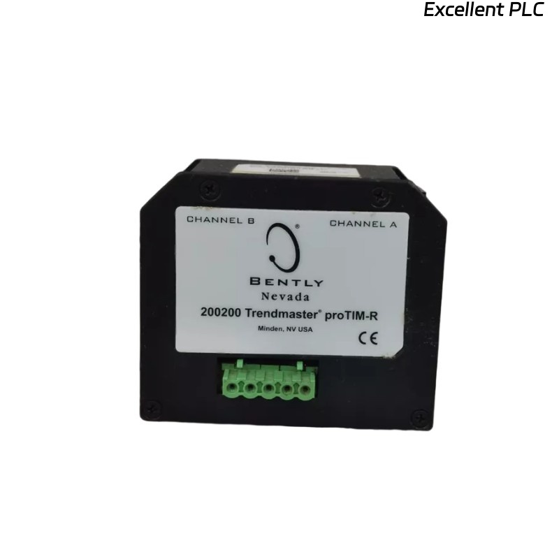
Faults related to the Bently Nevada 200200-01-01-05 Trendmaster module typically stem from wiring issues, interference, or improper configuration. These issues can cause inaccurate readings or complete signal loss.
Common Symptoms of 200200-01-01-05 Module Fault
- Erratic signal output during startup or while the system is under load
- Signal loss or failure to transmit data to the central monitoring system
- Frequent system alarms without actual mechanical failures
- Data discrepancies between different channels or sensors
Fault Diagnosis Process
Begin the diagnosis by checking the basic connections and verifying the configuration settings in the system software:
- Inspect all wiring for continuity and correct pinout
- Check the grounding and shielding of the input module
- Use diagnostic tools to measure the output signals and confirm consistency with expected readings
- Perform tests to identify any sources of electromagnetic interference (EMI) or physical damage to components
  // Fault Diagnosis Algorithm
  IF Signal_Loss OR Signal_Noise THEN
      Inspect_Cable_Routing();
      Validate_Grounding_And_Shielding();
  ELSE
      Recalibrate_Module_And_Check_Configuration();
  END_IF;
Common Causes of Module Fault
- Loose or corroded wiring connections
- Electromagnetic interference (EMI) from nearby equipment
- Improper grounding or shielding of the module input
- Incorrect configuration settings in the system software
- Physical damage to the module or associated cables
Diagnostic Methods and Tools
- Multimeter for continuity checks and verifying connections
- Oscilloscope for checking signal stability and detecting noise
- Vibration analysis tools to cross-check sensor readings with actual machinery performance
Corrective Actions and Recovery
- Replace or secure loose or damaged wiring and connectors
- Reroute cables to minimize interference from nearby electrical equipment
- Ground the module and sensor input properly to reduce EMI
- Recalibrate the module and reset configuration settings to the correct parameters
Real Troubleshooting Case
A case study from a field installation revealed signal inconsistencies during the commissioning of a pump monitoring system. The output was erratic during high-speed operation:
- Signal analysis showed significant noise during operational transitions
- After identifying EMI interference from a nearby motor, the cables were rerouted and the shielding grounded
Following these actions, the signal became stable, and the monitoring system provided accurate, consistent data throughout the operational cycle.
Troubleshooting FAQ
What should I do if my signal output is fluctuating?
Fluctuating signal output is typically caused by EMI or improper grounding. Ensure proper cable shielding and check the grounding connections.
How do I perform a continuity check on the 200200-01-01-05 module?
Use a multimeter to verify that there is a continuous connection through each wire. Also, ensure that there are no breaks in the signal path.
Can I continue using the module with intermittent signal loss?
No. Signal loss can indicate underlying wiring or configuration issues. Immediate troubleshooting is necessary to prevent further data corruption or false readings.
Final Technical Summary
The troubleshooting guide for the Bently Nevada 200200-01-01-05 Trendmaster proTim-R module provides a comprehensive process for diagnosing and resolving signal-related issues. Ensuring proper wiring, shielding, and configuration will maintain the integrity of your machinery monitoring system.