

Yokogawa SNB10D-425/CU2N installation failures are commonly caused by incorrect ESB bus configuration, improper Safety I/O allocation, or redundant power setup errors rather than defects within the Safety Node Unit itself. As a rack-mountable Safety Node Unit designed for ProSafe-RS architectures, the SNB10D-425/CU2N provides field signal acquisition, ESB bus communication, and power distribution for safety I/O modules. Proper Setup and Commissioning are critical for SIL-oriented applications. :contentReference[oaicite:0]{index=0}
Contents
- SNB10D-425/CU2N Safety Node Unit Overview
- SNB10D-425/CU2N Application in Safety Systems
- Engineering Planning Before Installation
- Cabinet Requirements for Safety Node Unit Installation
- Redundant Power Supply Preparation
- Incoming Hardware Inspection
- SNB10D-425/CU2N Installation Guide
- ESB Bus Setup Procedure
- Safety I/O Module Configuration
- Grounding and EMC Practices
- Initial Startup Verification
- SNB10D-425/CU2N Setup Workflow
- System Configuration Validation
- Commissioning Strategy
- Safety Loop Testing
- Redundancy Verification
- Project Documentation
- Real Commissioning Experience
- FAQ
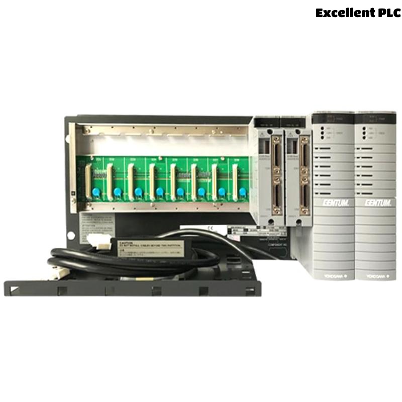
SNB10D-425/CU2N Safety Node Unit Overview
The SNB10D-425/CU2N is a rack-mountable Safety Node Unit used within Yokogawa ProSafe-RS systems. The unit supports ESB bus communication and serves as an interface between field safety signals and Safety Control Stations. It supports redundant power architectures and ESB connector unit integration. :contentReference[oaicite:1]{index=1}
SNB10D-425/CU2N Application in Safety Systems
- Emergency Shutdown Systems (ESD)
- Fire and Gas Systems (FGS)
- Burner Management Systems
- High Integrity Pressure Protection Systems
- Distributed Safety Architectures
Engineering Planning Before Installation
Successful projects begin with engineering preparation rather than hardware installation.
- Node quantity calculation
- Safety loop allocation
- ESB network topology review
- Power redundancy design
- Future expansion planning
Cabinet Requirements for Safety Node Unit Installation
- 19-inch rack cabinet
- Controlled temperature environment
- Dedicated grounding bar
- EMC-compliant wiring segregation
- Maintenance clearance access
For safety and EMC compliance, rack-mounted units should be installed inside a suitable metallic enclosure. :contentReference[oaicite:2]{index=2}
Redundant Power Supply Preparation
The “-425” version supports dual-redundant power supply architecture. Engineers should verify:
- Power source stability
- Voltage ratings
- Breaker sizing
- Redundant path availability
- Ground continuity
Incoming Hardware Inspection
- Inspect chassis integrity
- Verify model identification
- Inspect ESB connector unit
- Check mounting accessories
- Review shipment condition
SNB10D-425/CU2N Installation Guide
- Lock out incoming power.
- Prepare rack position.
- Install the Safety Node Unit.
- Secure mounting points.
- Verify alignment.
- Record installation information.
Mechanical stability reduces long-term maintenance issues.
ESB Bus Setup Procedure
- Verify bus routing
- Inspect connector seating
- Check bus addressing
- Confirm communication path
- Validate redundancy links
Safety I/O Module Configuration
- Digital input assignment
- Digital output allocation
- Analog channel grouping
- Safety voting arrangement
- Loop segregation review
Correct System Configuration minimizes startup delays.
Grounding and EMC Practices
- Verify protective earth connection
- Inspect cabinet bonding
- Check shield termination
- Separate signal and power cables
Initial Startup Verification
- Power LED inspection
- ESB communication review
- Module health verification
- Alarm monitoring
SNB10D-425/CU2N Setup Workflow
VERIFY POWER REDUNDANCY
CHECK ESB COMMUNICATION
VALIDATE NODE ADDRESS
VERIFY I/O STATUS
SAVE SYSTEM CONFIGURATION
RECORD BASELINE DATA
System Configuration Validation
- Node identification review
- I/O mapping verification
- Communication route validation
- Safety application review
- Redundancy parameter verification
Commissioning Strategy
Experienced engineers generally commission Safety Node Units in phases.
- Verify hardware.
- Validate communication.
- Check field wiring.
- Execute loop tests.
- Perform integrated safety testing.
Safety Loop Testing
- Input simulation
- Output verification
- Shutdown testing
- Alarm testing
- Recovery validation
Redundancy Verification
- Power failover testing
- Communication recovery testing
- Node availability verification
- Alarm response validation
Project Documentation
- Configuration backup
- Commissioning records
- Loop test reports
- Maintenance procedures
Real Commissioning Experience
During commissioning of an LNG facility, operators reported that several emergency shutdown inputs connected through an SNB10D-425/CU2N were unavailable.
Observed values:
- Supply voltage: 230 VAC
- ESB communication: normal
- Input response time: inconsistent
- Node diagnostics: healthy
Initial suspicion focused on the Safety Node Unit hardware.
However, engineers discovered duplicated channel assignments inside the System Configuration database.
After correcting the mapping:
- All inputs became visible
- Safety loops passed testing
- Communication remained stable
- Commissioning was completed successfully
We observed that database configuration errors produced symptoms identical to hardware faults.
SNB10D-425/CU2N Installation Guide FAQ
What is the main function of the SNB10D-425/CU2N?
It collects field safety signals, communicates through the ESB bus, and interfaces with the Safety Control Station. :contentReference[oaicite:3]{index=3}
Does the unit support redundant power?
Yes. The SNB10D-425/CU2N supports dual-redundant power architecture. :contentReference[oaicite:4]{index=4}
Why is System Configuration validation important?
Incorrect addressing and I/O mapping are among the most common causes of commissioning failures.
Summary: A successful Yokogawa SNB10D-425/CU2N Installation Guide requires structured Setup, accurate System Configuration, proper ESB bus integration, and disciplined Commissioning verification to ensure long-term safety system reliability.