

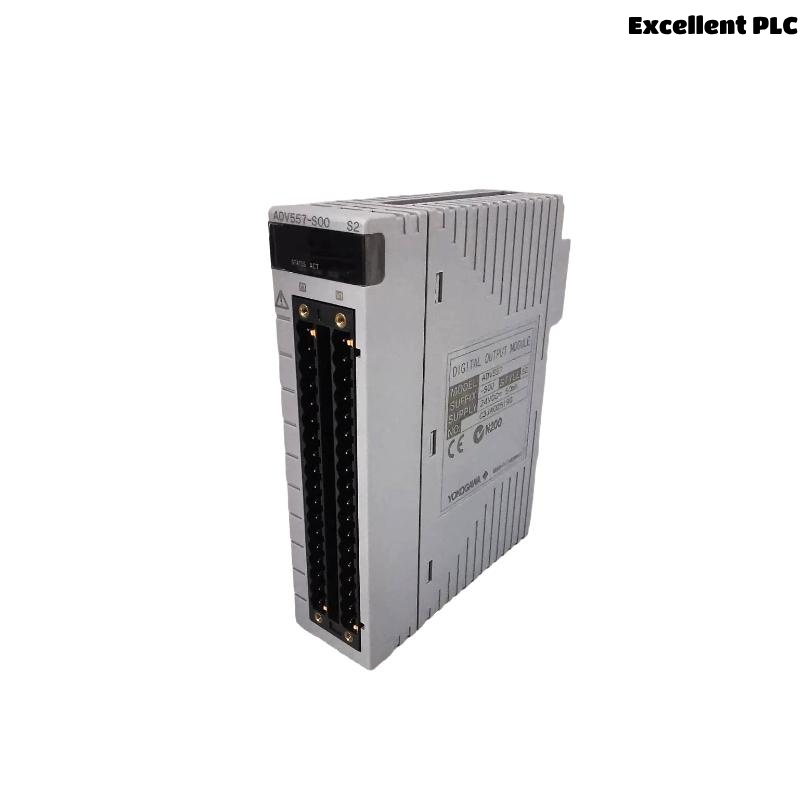
The Yokogawa ADV557 Digital Output Module is designed to provide reliable switching signals for industrial automation systems. When output failures occur, the root cause is usually found in field wiring, external power supplies, connected loads, or controller configuration rather than the module itself. Following a structured Troubleshooting procedure allows maintenance personnel to locate faults quickly, restore production efficiently, and avoid unnecessary module replacement.
Contents
- 1. Common Output Failure Symptoms
- 2. Troubleshooting Strategy
- 3. Typical Causes of Output Failure
- 4. Controller Logic Verification
- 5. Module Status Inspection
- 6. Output Voltage Diagnosis
- 7. Field Load Examination
- 8. Wiring Inspection Procedure
- 9. External Power Supply Analysis
- 10. System Configuration Verification
- 11. Recommended Diagnostic Workflow
- 12. Repair Recommendations
- 13. Functional Recovery Verification
- 14. Preventive Maintenance
- 15. Real Maintenance Case
- 16. FAQ
Common Output Failure Symptoms
Output problems may occur suddenly or develop gradually. Identifying the symptoms helps narrow the scope of the Fault Diagnosis.
- Output LED turns on but the field device does not respond
- Relay output operates intermittently
- Solenoid valve cannot be energized
- Motor starter receives no output signal
- Alarm indicator remains inactive
- Unexpected shutdown commands occur
- Output channel responds slower than expected
Troubleshooting Strategy
Effective troubleshooting follows the actual signal path from the controller to the field device. Instead of replacing the ADV557 immediately, engineers should first verify controller commands, inspect module status, measure electrical signals, and evaluate external components.
This systematic method significantly reduces maintenance time and prevents unnecessary hardware replacement.
Typical Causes of Output Failure
- Loose terminal connections
- Incorrect field wiring
- Blown external fuse
- Damaged relay coil
- Power supply voltage loss
- Incorrect output mapping
- Grounding problems
- Excessive load current
Controller Logic Verification
Before beginning electrical measurements, verify that the controller is issuing the correct output command.
- Check sequence execution
- Review interlock conditions
- Verify operator commands
- Inspect output status tags
- Confirm control logic execution
Module Status Inspection
- Check RUN indicator
- Inspect channel LEDs
- Review controller diagnostic messages
- Verify rack communication
- Inspect module seating
Output Voltage Diagnosis
| Measured Voltage | Possible Cause |
|---|---|
| 24 VDC | Normal output operation |
| 0 VDC | No controller output or open circuit |
| 8–15 VDC | High resistance or overloaded output |
| Fluctuating voltage | Loose wiring or unstable power source |
Measurements should always be taken while the field device is connected and operating under load conditions.
Field Load Examination
The connected load should always be verified before concluding that the module has failed.
- Measure relay coil resistance
- Inspect contactor current
- Verify solenoid valve operation
- Check suppression diodes
- Inspect output cable integrity
Wiring Inspection Procedure
- Verify terminal numbering
- Inspect cable continuity
- Confirm polarity
- Check marshalling cabinet wiring
- Inspect junction boxes
- Verify common return conductors
External Power Supply Analysis
A stable output module cannot operate correctly if the field power supply is unstable or incorrectly wired.
- Measure supply voltage
- Inspect power distribution
- Check protective fuses
- Verify common negative wiring
- Observe voltage during switching operations
System Configuration Verification
- Verify output channel assignments
- Review controller database
- Confirm downloaded project
- Check tag mapping
- Inspect logic references
Recommended Diagnostic Workflow
VERIFY CONTROLLER COMMAND
CHECK MODULE STATUS
MEASURE OUTPUT VOLTAGE
VERIFY FIELD POWER
INSPECT WIRING
CHECK OUTPUT LOAD
VERIFY SYSTEM CONFIGURATION
IDENTIFY ROOT CAUSE
PERFORM FUNCTION TEST
Following this workflow helps isolate faults efficiently while minimizing unnecessary maintenance activities.
Repair Recommendations
- Repair damaged field wiring
- Replace corroded terminal blocks
- Replace defective relay coils
- Correct configuration errors
- Repair unstable power circuits
- Replace the ADV557 module only after all external causes have been eliminated
Functional Recovery Verification
- Execute repeated output commands
- Confirm field device response
- Verify relay operation
- Observe controller diagnostics
- Monitor production during continuous operation
Preventive Maintenance
Regular preventive maintenance reduces the likelihood of unexpected output failures and extends overall system reliability.
- Inspect terminal tightness every six months
- Measure output voltage periodically
- Review diagnostic history
- Verify cabinet grounding annually
- Maintain updated configuration backups
Real Maintenance Case
At a power generation facility, operators reported that multiple cooling fan contactors controlled by an ADV557 Digital Output Module failed to start during equipment commissioning.
Controller diagnostics showed normal operation, and all output LEDs indicated active commands. Voltage measured directly at the ADV557 output terminals remained at approximately 24.1 VDC.
However, voltage measured at the contactor coils dropped below 10 VDC during startup. Engineers traced the problem to a deteriorated terminal strip inside the marshalling cabinet that introduced excessive resistance into the common return circuit.
After replacing the damaged terminal strip and tightening all associated wiring:
- All contactors energized correctly.
- Output voltage at the field devices returned to normal.
- No further alarms occurred during 96 hours of continuous operation.
- The ADV557 Digital Output Module continued operating normally without replacement.
This maintenance case demonstrates that field-side electrical measurements are essential because normal voltage at the module does not always guarantee adequate voltage at the connected equipment.
ADV557 Fault Diagnosis FAQ
Why is the output LED illuminated while the field device remains inactive?
This usually indicates an external problem such as damaged wiring, insufficient field power, excessive voltage drop, or a failed load rather than an internal module fault.
What should be checked before replacing the ADV557 Digital Output Module?
Verify controller logic, measure output voltage, inspect field wiring, confirm load condition, review System Configuration, and ensure stable external power before considering module replacement.
How can intermittent output failures be prevented?
Routine inspection of terminals, grounding systems, cable insulation, relay loads, and power supply stability can significantly reduce intermittent output problems and improve long-term system reliability.
Summary: Effective troubleshooting of the Yokogawa ADV557 Digital Output Module requires a disciplined diagnostic process that combines controller verification, electrical measurements, wiring inspection, load analysis, and configuration validation. By identifying the true root cause before replacing hardware, engineers can reduce maintenance costs, improve system availability, and ensure reliable digital output performance in demanding industrial environments.